Optical fiber interference water level sensor

A technology of water level sensor and optical fiber interference, which is applied in the direction of instruments, liquid level indicators, machines/engines, etc., can solve the problems of short service life, large error, limited transmission distance, etc., and achieve simple and exquisite structure, long service life, The effect of long transmission distance

Inactive Publication Date: 2015-06-10
JILIN UNIV
View PDF10 Cites 14 Cited by
  • Summary
  • Abstract
  • Description
  • Claims
  • Application Information

AI Technical Summary

Problems solved by technology

In the Chinese patent with the published patent No. CN102889914A, a float-type water level gauge using a reference water level is proposed. This float-type water level gauge has some defects. First, it is not resistant to electromagnetic interference, and the measurement accuracy is low and the error is too large , Secondly, due to the structure of the float, the float floats in the water, causing its mechanical structure to be subject to great wear and tear, and the reliability will be reduced
In the Chinese patent with the published patent number CN201731918U, an ultrasonic water level sensor is proposed, which uses the principle of ultrasonic transmission and reception to measure the liquid level. The disadvantage is that the ultrasonic transmission and reception have relatively high environmental requirements and cannot be applied In harsh or complex environments
As far as water level monitoring is concerned, these existing electrical sensors have many limitations, such as low safety, limited transmission distance, short service life, difficult networking, and inapplicability to harsh environments such as electromagnetic interference and strong corrosion.
Therefore, these water level sensors are increasingly unable to meet the needs of practical applications.

Method used


Image

  • Optical fiber interference water level sensor
  • Optical fiber interference water level sensor
  • Optical fiber interference water level sensor

Examples


Embodiment 1

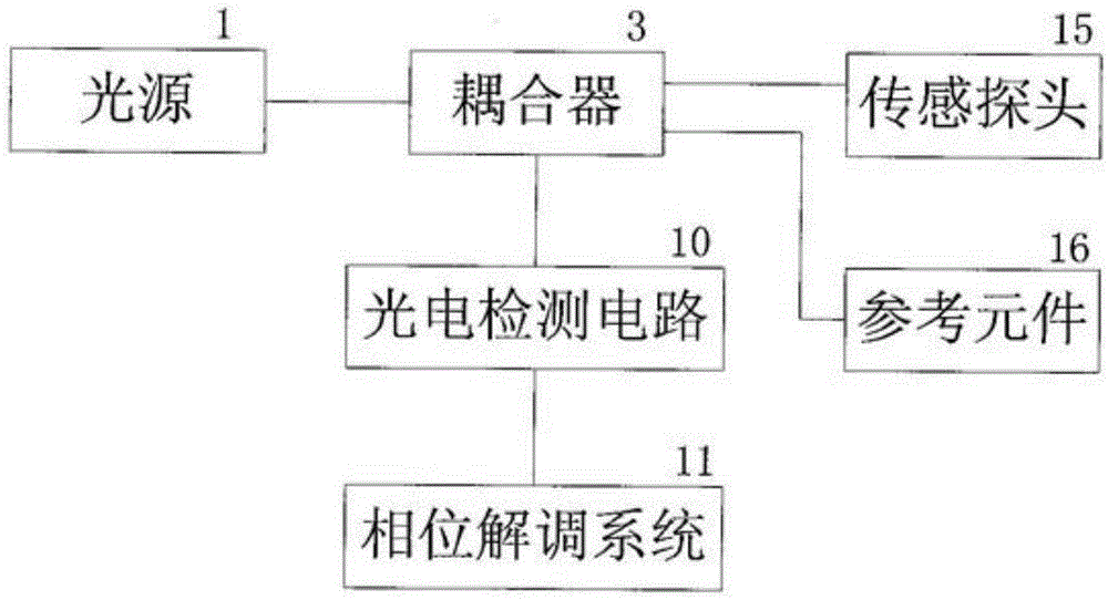
[0026] Such as figure 1 Shown is a system block diagram of a water level sensor based on fiber optic interferometry. The invention includes six parts: a light source module, a coupler, a sensing probe, a reference element, a photoelectric detection circuit, and a phase demodulation system. The light emitted by the light source enters the coupler, and the coupler divides the light into two paths. One path of light enters the sensor probe and is reflected back, and the other path passes through the reference element and is reflected back. The output end of the coupler is connected to the photoelectric detection circuit. The output signal of the photoelectric detection circuit enters the phase demodulation system for demodulation. Finally, the change of the water level is obtained by inversion of the phase difference change obtained from the demodulation.

Embodiment 2

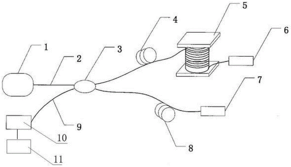
[0028] Such as figure 2 As shown, a water level sensor structure diagram based on optical fiber interferometry. The sensor structure includes a semiconductor laser 1, a light-guiding single-mode fiber 2, 4, 9, a 3dB coupler 3, a sensitive element 5, a first Faraday rotator 6, a second Faraday rotator 7, a reference fiber 8, and a photodetector 10 . It is characterized in that: the input end of the 3dB coupler 3 is connected to the semiconductor laser 1, and the output end of the coupler 3 is divided into two paths, one of which is connected to the sensitive element 5 and the first Faraday rotation mirror 6 through the single-mode fiber 4 to form a detection arm; The other path is directly connected to the second Faraday rotation mirror 7 via a single-mode optical fiber 8 to form a reference arm, and the 3dB coupler 3 is connected to the photodetector 10 via the light-guiding optical fiber 9, and the signal output by the photodetector 10 is collected by the acquisition card ...

Embodiment 3

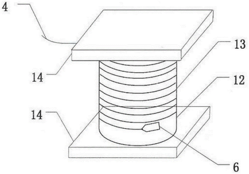
[0031] Such as image 3 , Figure 4 Shown is the sensitive element of the optical fiber interference water level sensor, and the structure diagram and section diagram of the sensing probe. exist image 3 , clearly shows that the sensitive element is a structure in which the single-mode detection fiber 13 is tightly wound around the variable cylinder 12, and one end of the detection fiber is connected to the first Faraday rotation mirror 6, and the other end is connected to the light guide fiber 4, and the upper and lower sides of the silica gel cylinder Two stainless steel thin plates 14 are fixed on the surface. The role of the stainless steel sheet is to increase the force-bearing area of ​​the sensing probe in the water, thereby increasing the sensitivity of the sensitive element. The compliance cylinder is a key part of the sensitive element, and its conversion efficiency and performance directly determine the characteristics of the sensitive element. The reason for cho...


PUM


Abstract

The invention discloses an optical fiber interference water level sensor. The optical fiber interference water level sensor is composed of a semiconductor laser device, a 3dB coupling device, a sensitive element, a Faraday polariscope, a light guide optical fiber, a photoelectric detector and a computer, wherein the sensitive element is a key part of the water level sensor and is used for converting the change of a water level into vertical strain and radial strain of the optical fiber so that the phase difference of two interference arms is changed; finally, the change of the water level is inverted by using the change of the phase difference. By the aid of the optical fiber interference water level sensor, the high-precision water level measurement can be realized, and the optical fiber interference water level sensor has the advantages of reliability, electromagnetic interference resistance, corrosion resistance, high sensitivity, simple and exquisite structure and the like, and is suitable for the environment needing high-precision water level monitoring.

Description

technical field [0001] The invention relates to the technical field of optical fiber sensing, in particular to an optical fiber water level sensing system based on a Michelson interferometer structure. Background technique [0002] High-precision water level sensors can be used to monitor the water level of reservoirs. When abnormal conditions such as floods or typhoons occur, if there is no effective water level monitoring in advance and the water level reaches the warning line, it will cause vicious accidents such as river embankment breaches and floods destroying embankments. These disasters will not only cause major economic losses , It will also threaten the safety of people's lives, so it is of great significance to the development of high-precision water level sensors. [0003] With the rapid development of optical fiber communication and optical fiber sensing technology, optical fiber sensors have also been widely used. Because the optical fiber sensor has the adva...

Claims


Application Information

Patent Timeline
Patent Type & Authority Applications(China)
IPC IPC(8): G01F23/292
Inventor 陈建冬刘野常天英崔洪亮于淼郞金鹏
Owner JILIN UNIV
Why Eureka
Try Eureka