Magnetic bearing electromagnetic force sensing device based on optical fiber grating and on-line measurement system

A technology of optical fiber gratings and sensing devices, which is applied in the direction of using optical devices to transmit sensing components, measuring the change force of optical properties of materials when they are stressed, and can solve the problem of not being able to obtain the electromagnetic force distribution of a magnetic levitation rotor. Point distributed measurement, small size and other issues, to achieve the effect of easy embedding, high resolution and good stability

Inactive Publication Date: 2008-11-05
WUHAN UNIV OF TECH
View PDF0 Cites 14 Cited by
  • Summary
  • Abstract
  • Description
  • Claims
  • Application Information

AI Technical Summary

Problems solved by technology

Since the rotor must be in contact with the probe of the tension / compression force sensor, the tension / compression force sensor can only measure the static electromagnetic force offline, and cannot obtain the electromagnetic force distribution of the magnetic levitation rotor in the rotating state; the magnetic bearing stator / The working air gap of the rotor is only about 0.3mm, and it is difficult for ordinary piezoelectric tension / compression force sensors to realize multi-point layout for multi-point distributed measurement of electromagnetic force. Solve the key problems of online measurement of electromagnetic force of magnetic bearing

Method used


Image

  • Magnetic bearing electromagnetic force sensing device based on optical fiber grating and on-line measurement system
  • Magnetic bearing electromagnetic force sensing device based on optical fiber grating and on-line measurement system
  • Magnetic bearing electromagnetic force sensing device based on optical fiber grating and on-line measurement system

Examples


Embodiment Construction

[0014] The specific embodiments of the present invention will be further described below in conjunction with the accompanying drawings.

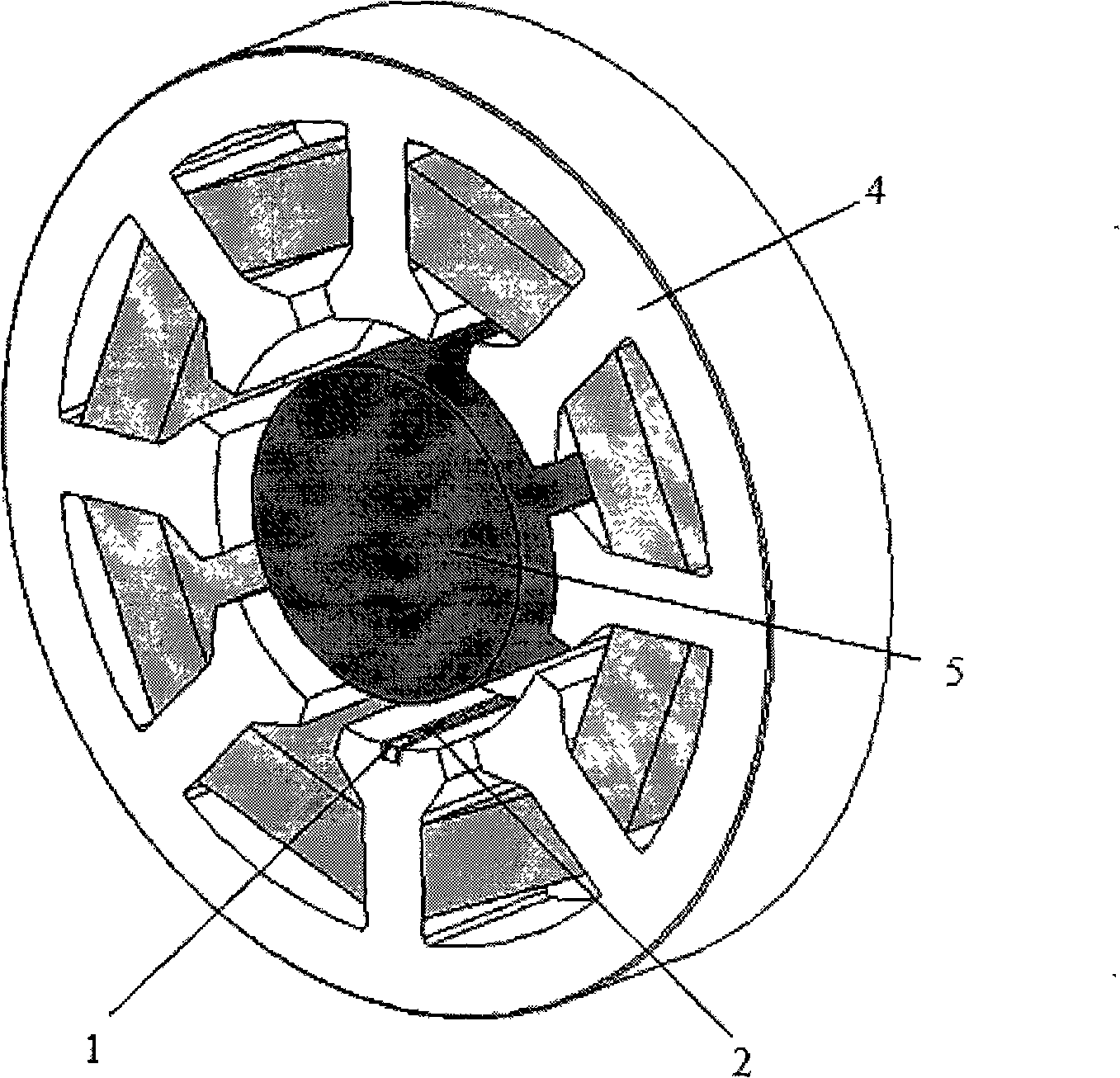
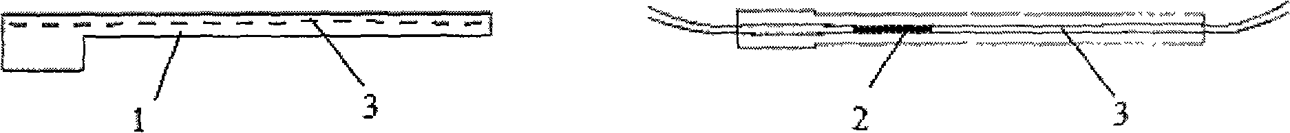
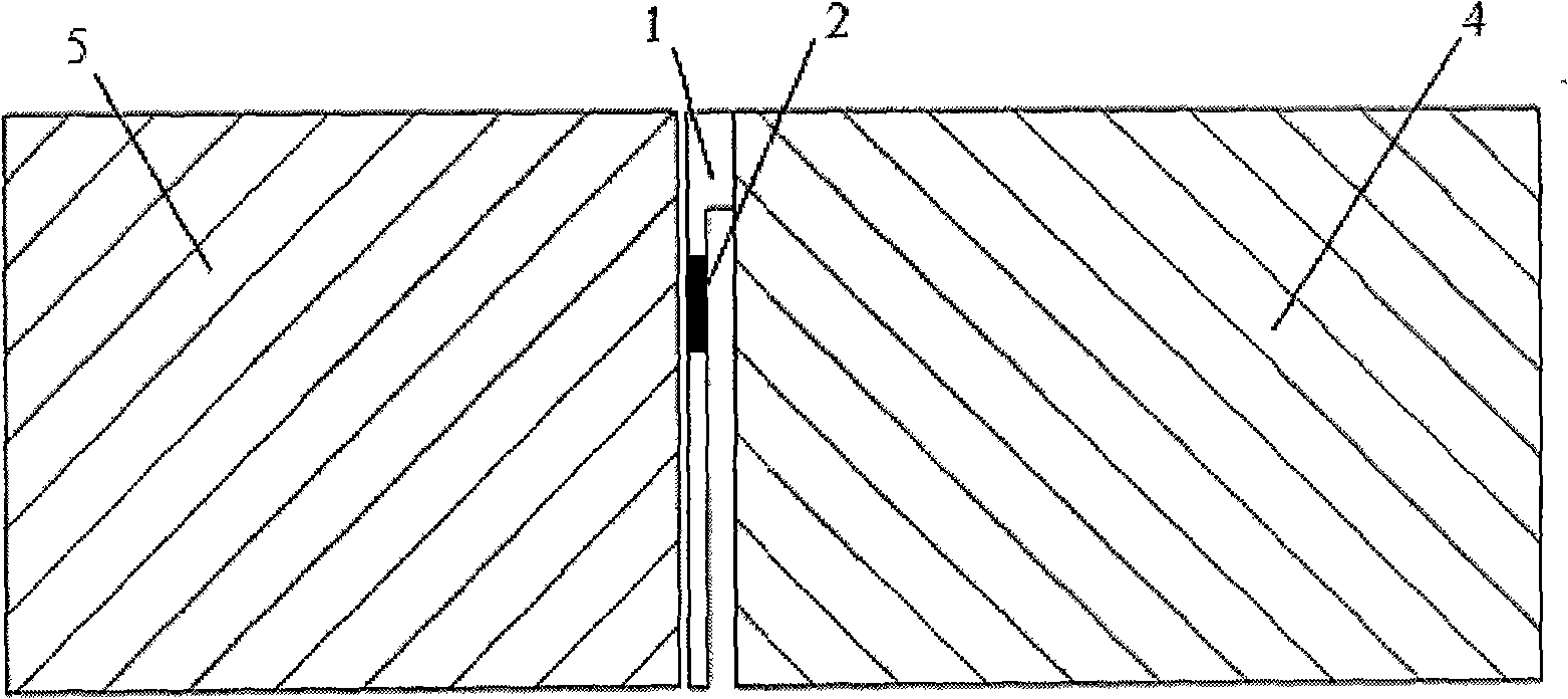
[0015] The fiber grating-based magnetic bearing electromagnetic force sensing device reflects the change of the magnetic bearing electromagnetic force through the fiber grating wavelength shift, and realizes the non-contact online measurement of the magnetic force. The sensing device is composed of an L-shaped magnetically conductive elastic element 1 , a fiber grating 2 , a magnetic bearing stator 4 and a magnetic bearing rotor 5 . The installation method is that a thin groove 3 is engraved on the central axis of the L-shaped magnetically conductive elastic element 1, and the fiber grating 2 is packaged in the thin groove 3 by pasting. Axial grooves are engraved on the bottom of the magnetic poles of the magnetic bearing stator 4, and the front-end convex part of the L-shaped magnetically conductive elastic element 1 is glued into the magne...


PUM


Abstract

The invention relates to an optical fiber grating magnetic force bearing electromagnetic force sensing device and an online measuring system, belonging to the optical fiber grating magnetic force sensing technical field, wherein the device comprises an L-shaped magnetic elastic unit 1 and an optical fiber grating 2 enclosed in the elastic unit groove, a magnetic force bearing stator 4, a magnetic force bearing rotor 5. The convex part of the L-shaped magnetic elastic unit is spliced in the groove at the bottom of the magnetic force bearing stator 4, and the other part is suspended in the air gap to form the cantilever structure. When in measurement, the wideband light source transmits the light with certain bandwidth and the conversion part into the optical fiber grating magnetic force sensing device through the light transmission, wherein the optical fiber grating 2 in the device generates the wavelength excursion due to the strain, according to the wavelength selection of the optical fiber grating, the required light is reflected, then is transmitted to the wavelength demodulation module through the light transmission and the conversion, which measures the change of the reflecting wavelength of the optical fiber grating, and the wavelength data are transmitted to the computer through the signal collection circuit. The wavelength is converted to the strain and reckons the electromagnetic force through the corresponding program, which realizes the record and the display of the electromagnetic force. The invention is suitable for the dotty distributing measurement of the electromagnetic force.

Description

technical field [0001] The invention belongs to the technical field of optical fiber grating electromagnetic force sensing, and is especially used for multi-point distributed measurement and online detection of electromagnetic force. technical background [0002] Magnetic bearing is a high-performance electromechanical integration product, mainly composed of bearing stator, rotor, displacement sensor, control system, power amplifier and other parts. Magnetic bearings use controllable electromagnetic force to suspend the rotor in space without any mechanical contact between the rotor and the stator. Compared with traditional bearings (rolling or sliding bearings), it has the advantages of no contact, no wear, long life, high speed, no need for lubrication and sealing, low power consumption, high precision, controllable and adjustable support characteristics, etc., and can be widely used It is used in military and industrial fields such as satellite attitude control, maglev f...

Claims


Application Information

Patent Timeline
Patent Type & Authority Applications(China)
IPC IPC(8): G01L1/24G01D5/353
Inventor 周祖德丁国平胡业发王晓光周次明蒋熙馨
Owner WUHAN UNIV OF TECH
Why Eureka
Try Eureka