Temperature self-compensating fiber grating rod force sensor and using method thereof

A fiber grating and force sensor technology, which is applied in the direction of force measurement, instrumentation, and the use of optical devices by measuring the change of optical properties of materials when they are stressed, can solve problems such as cross-sensitivity of fiber grating sensors, and achieve light weight, Simple structure and small volume

Inactive Publication Date: 2011-02-16
NORTHWESTERN POLYTECHNICAL UNIV
View PDF5 Cites 14 Cited by
  • Summary
  • Abstract
  • Description
  • Claims
  • Application Information

AI Technical Summary

Problems solved by technology

[0007] In order to avoid the deficiencies of the prior art, the present invention proposes a temperature self-compensating fiber grating rod force sensor and its use method, which can eliminate the influence of temperature while measuring the strain, has a simple manufacturing process, and solves the problem of fiber grating sensor crossover. sensitive issue

Method used


Image

  • Temperature self-compensating fiber grating rod force sensor and using method thereof
  • Temperature self-compensating fiber grating rod force sensor and using method thereof
  • Temperature self-compensating fiber grating rod force sensor and using method thereof

Examples


Embodiment 2

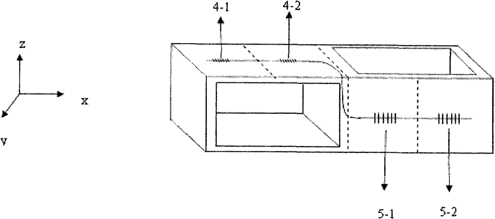
[0049] Embodiment 2: see attached figure 2 , the difference from Example 1 is that the first FBG strain sensor 4 and the second FBG strain sensor 5 are bare fiber Bragg gratings, and the first FBG strain sensor 4 consists of two bare FBG strain sensors 4 -1, 4-2 connected in sequence and pasted on the central axis of the surface, the second fiber grating strain sensor 5 is composed of two bare fiber Bragg gratings 5-1, 5-2 connected in sequence and pasted on the surface on the central axis. When the rod force sensor is bent and deformed, the center wavelength drift of the first fiber Bragg grating strain sensor 4 takes the average value of the center wavelength drift of the bare fiber Bragg grating 4-1, 4-2; the center wavelength of the second fiber Bragg grating strain sensor 5 The drift is the average value of the center wavelength drift of the bare fiber Bragg gratings 5-1 and 5-2.

Embodiment 3

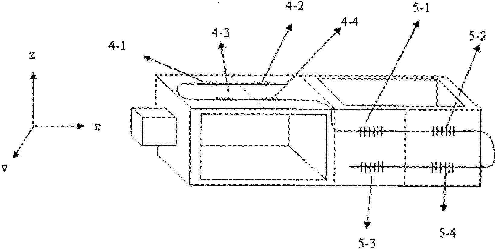
[0050] .Embodiment 3: see attached image 3 , the difference from Example 1 is that the first FBG strain sensor 4 and the second FBG strain sensor 5 are bare long-period fiber gratings, and the first FBG strain sensor 4 is composed of four bare long-period optical fibers The gratings 4-1, 4-2, 4-3, and 4-4 are sequentially connected to form and pasted on the surface, arranged in two rows up and down, and parallel to the upper and lower sides of the surface. The second fiber grating strain sensor 5 is composed of two bare long-period fiber gratings 5-1, 5-2, 5-3, 5-4 sequentially connected and pasted on the central axis of the surface. When the rod force sensor is bent and deformed, the center wavelength drift of the first fiber Bragg grating strain sensor 4 is the average value of the center wavelength drift of the bare fiber Bragg grating 4-1, 4-2, 4-3, 4-4; The center wavelength shift of the fiber Bragg grating strain sensor 5 is the average value of the center wavelength s...


PUM


Abstract

The invention relates to a fiber grating rod force sensor and a using method thereof. The force sensor is characterized in that: rectangular hollow rectangular frames of two associated parallel girders smoothly move and are vertically and fixedly connected; a first fiber grating strain sensor is adhered to a plane of the first associated parallel girder parallel to the rectangular hollow rectangular frames; a second fiber grating strain sensor is adhered to a plane of the second associated parallel girder parallel to the rectangular hollow rectangular frames; and the first fiber grating strain sensor and the second fiber grating strain sensor are connected in series. The sensor has the characteristics of anti-electromagnetic interference, high precision, quick dynamic response, small volume, light weight, simple structure and the like, and also has reliability, stability and simpleness. In addition, the temperature self-compensating fiber grating rod force sensor has relatively low cost, is applied to narrow space, and is subjected to temperature compensation when measuring the stress of an elastic element.

Description

technical field [0001] The invention relates to an optical fiber grating rod force sensor and a use method, which can eliminate the influence of temperature on the optical fiber grating sensor and belongs to the field of optical fiber sensing. Background technique [0002] Fiber Bragg grating sensing is a new type of sensing principle. It uses light waves as signal carriers and uses wavelength modulation. It is not affected by light intensity and has stable signals. It has good sensing performance in various occasions of structural engineering. The temperature and strain sensor made by using the fiber grating principle can effectively measure the temperature and strain of the structure, and the manufactured sensor has the advantages of small size, high measurement accuracy, anti-electromagnetic interference, corrosion resistance, good reliability and stability, and good durability. Etc. [0003] In the rod force sensing system, the traditional rod force sensing principle mo...

Claims


Application Information

Patent Timeline
Patent Type & Authority Applications(China)
IPC IPC(8): G01B11/16G01L1/24
Inventor 杨德兴张铭姜亚军
Owner NORTHWESTERN POLYTECHNICAL UNIV
Why Eureka
Try Eureka