
H-bridge cascaded active power filter and control method thereof

A source filter, control method technology, applied in harmonic reduction device, AC network to reduce harmonic/ripple, single-network parallel feeding arrangement, etc., can solve compensation current detection error, inaccurate separation, capacitance voltage Difficult to balance control and other problems to achieve the effect of high equivalent switching frequency

Inactive Publication Date: 2012-06-27
HUATIAN ENG & TECH CORP MCC
View PDF4 Cites 29 Cited by
  • Summary
  • Abstract
  • Description
  • Claims
  • Application Information

AI Technical Summary

Problems solved by technology

[0003] The compensation current detection method of the H-bridge cascaded active filter often adopts the harmonic and reactive power detection method based on the synchronous rotating coordinate system. This detection method can accurately detect the compensation current when the grid voltage is symmetrical. When the grid voltage is not When symmetrical, this detection method cannot accurately separate the fundamental positive sequence active and reactive currents, resulting in large errors in compensation current detection
[0004] The DC capacitors of each H-bridge module in the H-bridge cascaded active filter are independent of each other. Due to the difference in the switching loss of each H-bridge, the dispersion of parameters, and the trigger pulse delay of the switching device, the capacitor voltage will be unbalanced. These unbalanced phenomena will lead to inconsistencies in the voltages borne by the H-bridge power switches, threatening the safe operation of the active filter, and the balanced control of the capacitor voltages of each H-bridge becomes a difficult point

Method used


Image

  • H-bridge cascaded active power filter and control method thereof
  • H-bridge cascaded active power filter and control method thereof
  • H-bridge cascaded active power filter and control method thereof

Examples


Embodiment Construction

[0030] The present invention will be described in detail below in conjunction with the accompanying drawings.

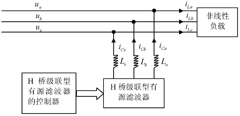
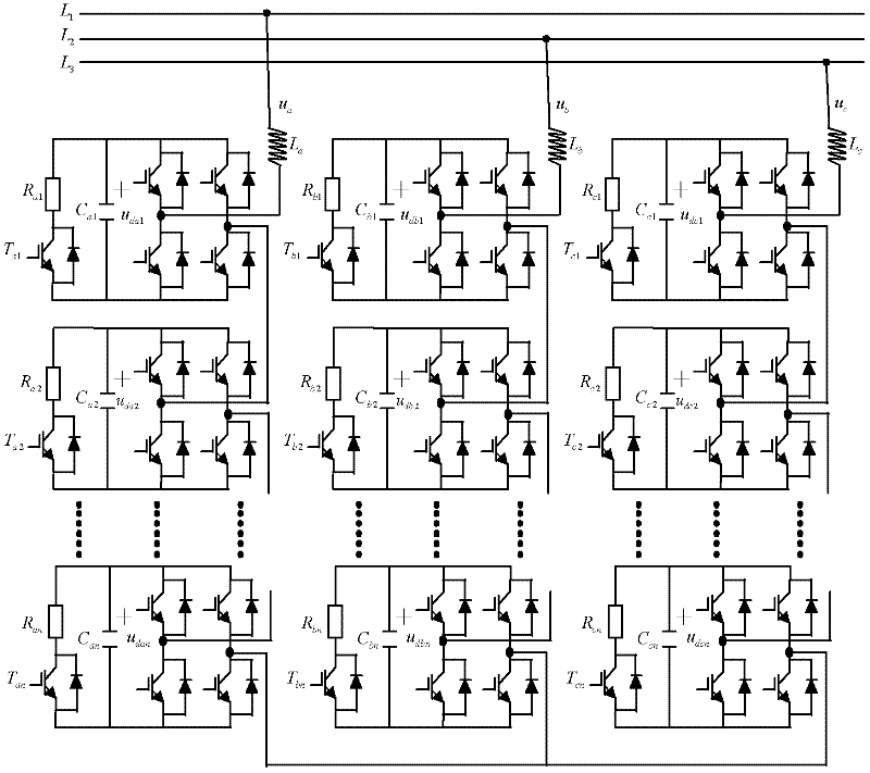
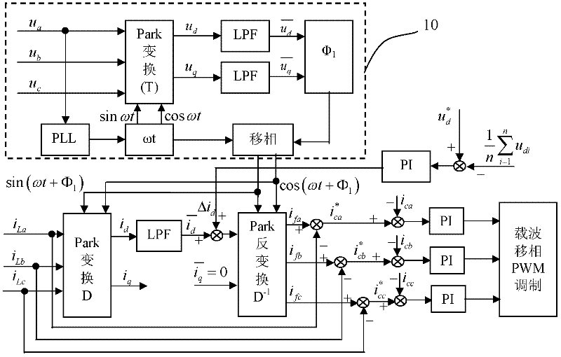
[0031] The steps of the control method of the H-bridge cascaded active filter of the present invention include: detecting the nonlinear load current; calculating the expected compensation current value; obtaining the reference current value of the active filter; making the output current of the active filter track Reference current; the trigger signal of the cascaded H-bridge power device is obtained through carrier phase-shift pulse width modulation to drive the power device of the main circuit. The grid-side current after compensation only contains the fundamental positive-sequence active current. The capacitor voltage of the H-bridge cascade unit passes through the voltage controller, and its output is the positive-sequence active current lost by the active filter. The capacitor voltage of each H-bridge is discharged and controlled through its own power tube and d...


PUM


Abstract

The invention discloses a control method of an H-bridge cascaded active power filter. The control method is designed aiming at solving the problem of low accuracy because of asymmetrical voltage in the existing method. The control method comprises the steps that: nonlinear load current is detected to obtain an expected compensating current value; the reference current value of the active power filter is obtained; the active power filter outputs current to track reference current; and the trigger signal of a cascaded H-bridge power device is obtained through carrier phase-shift pulse width modulation to drive a main circuit power device. The method for detecting the nonlinear load current is an improved synchronous reference coordinate system detection method based on fundamental-wave positive sequence voltage phase locking. The invention additionally discloses the three-phase star-connected H-bridge cascaded active power filter, wherein the capacitance and the voltage of a filter unit are controlled through a voltage controller, and the on and off of a power switch is controlled through a pulse width modulation strategy to adjust an equivalent resistance value. Under the situations that power voltage is asymmetrical and is distorted, the compensating current required by a load can be accurately detected.

Description

technical field [0001] The invention relates to an H-bridge cascaded active filter and a control method thereof. Background technique [0002] With the development of power electronics technology, a large number of non-linear loads have been added to the power supply system, especially static converters that work in switching mode, which will inevitably generate non-sinusoidal waveforms and inject harmonics into the grid, making the voltage in the grid And the current waveform distortion is getting more and more serious, and the harmonic pollution in the power grid is getting worse. In order to overcome the deficiencies of traditional passive filters, an important trend of harmonic suppression devices is to use active filters (APF). Parallel APF is the most basic and the most widely used one at present. It injects into the power grid by generating compensation current equal to the harmonic and reactive components in the load current and with a phase difference of 180°, so ...

Claims


Application Information

Patent Timeline
Patent Type & Authority Applications(China)
IPC IPC(8): H02J3/01H02J3/38
CPCY02E40/40
Inventor 姚自立陆红学李晟夏华郭智文
Owner HUATIAN ENG & TECH CORP MCC
Learn More