Switch type power amplification device and method for simulating current transformation control

A power amplification, switching type technology, applied in the output power conversion device, the conversion of AC power input to AC power output, and the conversion of AC power input to DC power output, etc., can solve the problem of small control bandwidth and dynamic response time of power amplifier devices. It can improve the equivalent switching frequency, reduce the dynamic response time, and improve the adaptability.

Inactive Publication Date: 2017-01-04
SHANGHAI KELIANG INFORMATION ENG
View PDF10 Cites 4 Cited by
  • Summary
  • Abstract
  • Description
  • Claims
  • Application Information

AI Technical Summary

Problems solved by technology

However, there are the following problems: 1) There are certain safety hazards in the high-speed rotating mechanical parts of the motor stand; 2) It is difficult to test extreme working conditions and various fault conditions; 3) The motor control characteristics of the simulated mechanical load are very demanding; 4) It is difficult to flexibly change the type and parameters of the test motor
[0007] Although the "PHIL" test scheme for motor control drives has many advantages in theory, in practice, its accuracy and effectiveness are largely limited by the performance of the power amplifier
The power amplification device in the "PHIL" test scheme involved in the prior art has small control bandwidth, long dynamic response time, poor adaptability to the tested motor control drive device, and cannot adapt to the test motor control drive device with different technical characteristics. , resulting in less practical

Method used


Image

  • Switch type power amplification device and method for simulating current transformation control
  • Switch type power amplification device and method for simulating current transformation control
  • Switch type power amplification device and method for simulating current transformation control

Examples


Embodiment Construction

[0027] In order to make the object, technical solution and advantages of the present invention clearer, various embodiments of the present invention will be described in detail below in conjunction with the accompanying drawings. However, those of ordinary skill in the art can understand that, in each implementation manner of the present invention, many technical details are provided for readers to better understand the present application. However, even without these technical details and various changes and modifications based on the following implementation modes, the technical solution claimed in this application can also be realized.

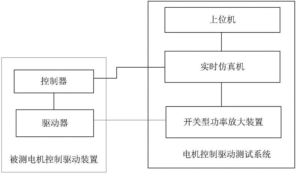
[0028] The switch type power amplification device involved in the embodiment of the present invention can be applied to such as figure 1 The power hardware-in-the-loop (PHIL)-based motor control drive test scenario is shown. Among them, the motor control drive test system consists of a host computer, a real-time simulator and a switch-type...


PUM


Abstract

The invention relates to the technical field of power electronics, and discloses a switch type power amplification device and a method for simulating current transformation control. The switch type power amplification device comprises a simulation-side current transformation circuit, a direct-current bus circuit and a power-side current transformation circuit which are sequentially connected with one another. The simulation-side current transformation circuit comprises an input filter, parallel filter inductors and three-phase two-level parallel arms which are sequentially connected with one another; the input filter is of an LC structure, capacitors are arranged on a side where the parallel filter inductors are arranged, 3n arms are connected with one another on direct-current sides in parallel to form each three-phase two-level parallel arm, each phase of each three-phase two-level parallel arm is provided with the n corresponding arms, and the n is larger than or equal to 2; filter inductors are serially connected with a middle point of each arm, and LCL type filters can be jointly equivalently formed by the filter inductors and the input filter after the filter inductors are subjected to phase separation and are connected with one another in parallel; switches in the three-phase two-level parallel arms are power electronic full-control type devices. The switch type power amplification device and the method have the advantages that the control bandwidth of the switch type power amplification device can be increased, the dynamic response time can be shortened, the adaptability to measured motor control driving devices with different technical characteristics can be improved, and the switch type power amplification device and the method are high in practicality.

Description

technical field [0001] The invention relates to the technical field of power electronics, in particular to a switch-type power amplifier and an analog converter control method. Background technique [0002] A motor is a device that uses an electromagnetic field as a medium to convert mechanical energy and electrical energy. According to the direction of energy conversion, it is divided into two working modes: electric motor (that is, converting electrical energy into mechanical energy) and generator (that is, converting mechanical energy into electrical energy). According to the different forms of mechanical motion, it can be divided into rotary motor and linear motor. This article involves It is a rotating electrical machine, and the electrical machines mentioned later are also rotating electrical machines. [0003] The working characteristics of the motor are not only related to its body parameters and process, but also mainly determined by the control drive device. Diff...

Claims


Application Information

Patent Timeline
IPC IPC(8): G05B23/02H02M7/217H02M7/5387H02M5/458
CPCG05B23/02H02M5/4585H02M7/217H02M7/5387
Inventor 董亮邹毅军李鸿彪王天民
Owner SHANGHAI KELIANG INFORMATION ENG
Why Eureka
Try Eureka