System for realizing network extension and protection functions with wave-division multiplexing annular optical access networks and method for realizing network extension and protection functions with wave-division multiplexing annular optical access networks

A technology of wavelength division multiplexing and network expansion, applied in the field of optical communication, which can solve the problems of inability to dynamically schedule the system and inconvenient scheduling of system wavelengths.

Inactive Publication Date: 2012-06-27
SHANGHAI UNIV
View PDF2 Cites 21 Cited by
  • Summary
  • Abstract
  • Description
  • Claims
  • Application Information

AI Technical Summary

Problems solved by technology

At present, the research on WDM-PON is mainly based on static wavelength allocation. The downlink of wavelengths in RN is fixed. When system users change, dynamic sch...

Method used


Image

  • System for realizing network extension and protection functions with wave-division multiplexing annular optical access networks and method for realizing network extension and protection functions with wave-division multiplexing annular optical access networks
  • System for realizing network extension and protection functions with wave-division multiplexing annular optical access networks and method for realizing network extension and protection functions with wave-division multiplexing annular optical access networks
  • System for realizing network extension and protection functions with wave-division multiplexing annular optical access networks and method for realizing network extension and protection functions with wave-division multiplexing annular optical access networks

Examples


Embodiment 1

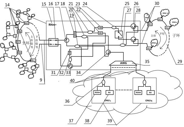
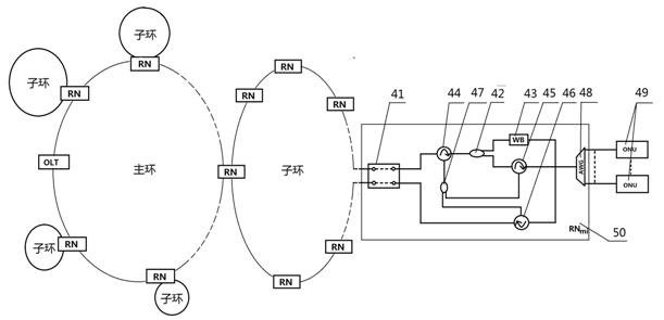
[0035] see Figure 1~Figure 4 , this wavelength division multiplexing ring wavelength division multiplexing ring optical access network realizes the system of network expansion and protection function, the optical link terminal OLT (1) connects M A main ring remote node RN (14) forms a ring structure, which is called a main ring here. Each remote node RN of the main ring a (14) Each sub-ring (29) is connected to each sub-ring (29) by connecting the optical fiber (15), and each sub-ring (29) is connected to n remote nodes RNb (5) Connected, the remote node RN of the main ring a and the remote node RN on each sub-ring b (15,16) respectively connect q optical network units ONU through distribution optical fiber (55) b (49); and, the main ring (1) passes each main ring remote node RN a (14) Directly connect q optical network units ONU a It is characterized by:

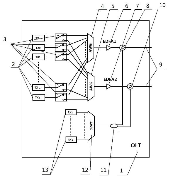
[0036] 1) The optical link terminal OLT (1) has Q optical transmitters (2) respectively connected to two arrayed w...

Embodiment 2

[0042] This WDM ring optical access network realizes network expansion and protection function method, adopts the system of embodiment 1 to operate as follows:

[0043] 1) There are Q wavelengths belonging to C-band and L-band, among which the wavelengths of C-band are supplied to each remote node RN on the main ring (1) a (14) Directly connected optical network unit ONU a (39) use, the L-band wavelength is for the remote node RN of each sub-ring b Optical Network Unit ONU under (50) b (49) USED. where in normal mode, such as Figure 5 As shown, in the downlink, the optical link terminal OLT (1) Q optical transmitters (2) send signals through Q optical switches (3) and then transmit them to the first arrayed waveguide grating AWG (4) for multiplexing, and then Through the first EDFA1 (6) and the optical circulator 1 (8), the output from its right port enters the main ring feeder fiber (9). Such as Image 6 As shown, the downlink signal is transmitted clockwise in the mai...

Embodiment 3

[0048] The wavelength division multiplexing ring optical access network realizes the network expansion and protection function method, adopts the system of embodiment 1 to operate as follows:

[0049] 1) if Figure 8 , Figure 9 As shown in , when the sub-ring feeder fiber fails, the corresponding main ring remote node RN a (14) When working in protection mode: here to convert the remote node RN m* (15) and its connected sub-ring (29) as an example, when the feeder fiber fails, the remote node RN m* The optical switch (25) receives the control signaling from the optical link terminal OLT (1), and is in the closed state. At this time, for Figure 9 , sub-ring remote node RN m1 The downlink and uplink transmissions are still transmitted in the above way; for RN m2 ...RN mn The downlink signal λ m21 ...λ m2q ...λ mmq ...λ mnq From remote node RN m* The optical switch (25) reaches the third optical circulator (28), is input from its left port, and the output from the lo...


PUM


Abstract

The invention relates to a system for realizing network extension and protection functions with wave-division multiplexing annular optical access networks and a method for realizing the network extension and protection functions with the wave-division multiplexing annular optical access networks. The system is characterized in that an OLT (optical link terminal) is connected with M RNs (remote nodes) through an optical fiber to form an annular network, and the remote nodes are connected with ONUs (optical network units) through a distributed optical fiber, wherein the optical link terminal mainly comprises Q=Mq (1+n) optical transmitters, Q receivers, Mq transmitting C wave-band wavelength, Mnq transmitting L wave-band wavelength, Q 1X2 optical switches, three AWGs (arrayed waveguide gratings) of an identical structure and with Q ports, two EDFAs (erbium-doped fiber amplifiers), two optical circulators and a 2X1 coupler; and each remote node on a main ring mainly comprises a 2X2 optical switch, a 1X2 optical switch, two WBs (wavelength blockers), a CWDM (coarse wavelength division multiplexing), four common circulators, a closed circulator, six couplers and an arrayed waveguide grating. A feeder optical fiber is protected by the aid of use of the optical switches at the OLT end and designs of the annular structures and RN structures. By means of effective arrangement of the RN nodes, network scale extension can be realized, typical annular tangent topological structures are realized, network coverage area is greatly widened, and the quantity of users is greatly increased. The system realizes dynamic dispatching of the wavelength by adjusting the wavelength blockers and changing operating ports of the arrayed waveguide gratings, and achieves balance between the cost and the performance.

Description

technical field [0001] The invention relates to the field of optical communication, in particular to a system and method for realizing network expansion and protection functions of a wavelength division multiplexing ring optical access network. Background technique [0002] The WDM-PON technology of wavelength division multiplexing passive optical network can upgrade the bandwidth without changing the physical infrastructure equipment, greatly improve the transmission capacity of the network, and realize virtual point-to-point transmission. It has broad application prospects in the optical access network and is considered to be the final choice for the future evolution of FTTx. At present, the research on WDM-PON is mainly based on static wavelength allocation. The downlink of wavelengths in RN is fixed. When system users change, dynamic scheduling of wavelengths cannot be realized within the system. When users change or increase or decrease , it brings inconvenience to the...

Claims


Application Information

Patent Timeline
IPC IPC(8): H04B10/12H04Q11/00H04L12/42H04B10/275
Inventor 邵奇甘朝钦时琼玲王瑞雪戚永前
Owner SHANGHAI UNIV
Why Eureka
Try Eureka