Bee toxicology experiment contamination automatic feeding device and application thereof

A feeder and bee technology, applied in applications, beekeeping, animal husbandry, etc., can solve problems affecting accuracy, waste of raw materials, honey dripping, etc., and achieve the effect of simple structure and accurate feeding amount

Active Publication Date: 2012-07-04
RES CENT FOR ECO ENVIRONMENTAL SCI THE CHINESE ACAD OF SCI
View PDF9 Cites 7 Cited by
  • Summary
  • Abstract
  • Description
  • Claims
  • Application Information

AI Technical Summary

Problems solved by technology

And every group of 60 honeybees can only actually consume a few milliliters of poisoned honey in 3 to 4 hours. Traditional large-scale bee automatic feeders such as hydraulic bee feeders (authorized announcement number: CN 2440323Y), a kind of The automatic control bee feeder (authorized announcement number: CN 201185600Y) has a complex structure and many pipes, which not only causes waste of raw materials in the experiment process, but also problems such as pipe residues will seriously affect the accuracy of the experiment
[0005] In the general bee feeding tube experiment, the feeding tube is usually used to droop, and gravity is used to let the poisoned honey flow down automatically. Feed, but this design will inevitably cause the honey to drop due to its own gravity during use, which will affect the accuracy of the experiment

Method used


Image

  • Bee toxicology experiment contamination automatic feeding device and application thereof
  • Bee toxicology experiment contamination automatic feeding device and application thereof
  • Bee toxicology experiment contamination automatic feeding device and application thereof

Examples


Embodiment Construction

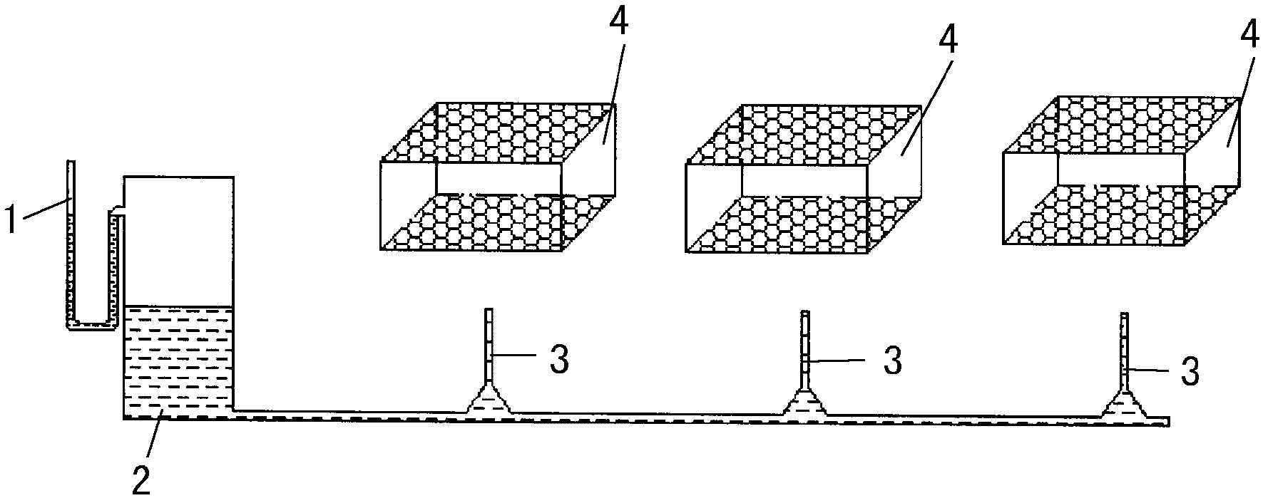
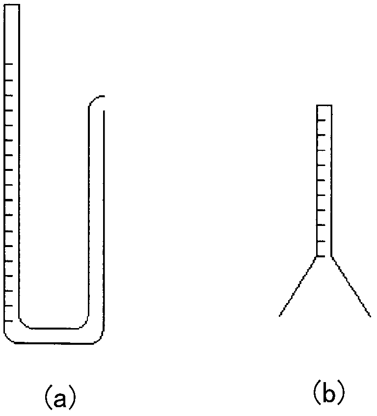
[0027] see figure 1 , the present invention comprises a U-shaped tube 1, a liquid reservoir 2, a feeder 3 and a bee box 4, such as figure 1 shown. Among them, the bee box 4 except the upper and lower sides, the four sides are wooden box walls, the size is 10.5cm*10.0cm*8.0cm, the thickness of the box wall is 1cm, 20 bees are placed in each box, and the upper and lower sides of the box wall are used The gauze was tightly sealed to prevent the bees from escaping during the experiment.

[0028] Its specific structure is: one side port of the U-shaped tube 1 is directly connected to the liquid reservoir 2 (according to the direction shown in the figure, it refers to the right side port of the U-shaped tube, which is referred to as the right side for convenience in the following description), The port on the other side of the U-shaped tube 1 that is not connected to the liquid reservoir 2 (according to the direction shown in the figure, refers to the left port of the U-shaped tub...


PUM


Abstract

The invention relates to a bee toxicology experiment contamination automatic feeding device, which is mainly and structurally characterized by comprising a graduated U-shaped pipe, wherein an end opening of one side of the U-shaped pipe is connected with a sealed liquid storage device, an end opening of one side of the U-shaped pipe not connected with the liquid storage device is higher than an interface of the liquid storage device, the bottom of the liquid storage device is connected with a plurality of feeding devices through pipelines for forming a communication device, feeding openings of the feeding devices respectively and upwards penetrate into corresponding bee boxes, and the total area of the liquid level in the feeding openings is identical to the area of the liquid level of one side of the U-shaped pipe not connected with the liquid storage device. The bee toxicology experiment contamination automatic feeding device overcomes the defects of adverse factors when the traditional large-range bee automatic feeding device is used for bee toxicology experiment operation, and the pipeline structure of the bee automatic feeding device is simplified, so the bee toxicology experiment contamination automatic feeding device is more suitable for small-range bee feeding. Simultaneously, the feeding opening is upward, the communication device principle is utilized for ensuring the liquid level height, and the honey loss caused by the downward pipe opening is avoided. The consumed contaminated honey quantity can be accurately read out through scales on the U-shaped pipe.

Description

technical field [0001] The invention belongs to the field of feeder equipment, and in particular relates to an automatic feeder for honeybee poisoning experiments. [0002] The present invention also relates to the application of the above-mentioned automatic feeder for bee toxicology experiment. technical background [0003] Bees are an important class of environmental organisms. They not only collect flowers to make honey, but also impart pollen, which contributes to the increase of crop production and has important economic value. The use of chemical substances such as pesticides is very harmful to bees, and pesticides such as organophosphorus, carbamates, and pyrethroids are highly toxic to bees. A large number of bees die due to the use of these pollutants, which not only directly reduces honey production and affects crop pollination rates, but also pesticides and toxic metabolites remaining in honey are harmful to human health. Therefore, it is of great significance ...

Claims


Application Information

Patent Timeline
Patent Type & Authority Applications(China)
IPC IPC(8): A01K53/00
Inventor 李建中王瀛寰王会利张艳峰
Owner RES CENT FOR ECO ENVIRONMENTAL SCI THE CHINESE ACAD OF SCI
Why Eureka
Try Eureka