Two-dimensional laser cutting machine

A two-dimensional laser and laser cutting head technology, applied in the field of improvement, can solve the problems of large motion inertia, bulkiness, and low operating accuracy

Inactive Publication Date: 2012-07-04
江苏扬力数控机床有限公司
View PDF7 Cites 7 Cited by
  • Summary
  • Abstract
  • Description
  • Claims
  • Application Information

AI Technical Summary

Problems solved by technology

However, the structure of the laser head seat used in this solution is still relatively large and bulky, resulting in large motion inertia, which in turn

Method used


Image

  • Two-dimensional laser cutting machine
  • Two-dimensional laser cutting machine
  • Two-dimensional laser cutting machine

Examples


Embodiment Construction

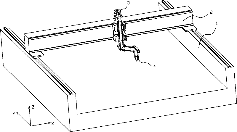
[0016] The invention as figure 1 , 2 As shown, the laser cutting machine includes a body 1, a beam 2, a laser cutting head 4 and a laser generator. The body 1 and the beam 2 are connected to each other through an X-guiding guide provided on the body, and the side of the beam is provided with a Y Guide rail, the laser cutting head 4 is movably connected to the Y guide rail on the side of the beam 2 through the local motion mechanism 3 (in figure 1 The X, Y, Z coordinate system is marked in the middle);

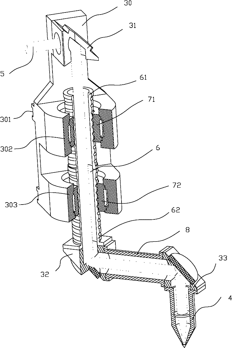
[0017] The local motion mechanism includes a Y-direction motion support 30, a bidirectional hollow screw shaft 6, a light guide cylinder 8, a screw nut 1 71, a drive motor 1, a screw nut 2 72, a drive motor 2 and at least two mirror groups (reflector mirror group one 32, mirror group two 33);

[0018] The back side of the Y-direction movement support 30 is provided with a chute 301 for connecting the Y guide rail; the front side of the Y-direction movement support 30 is prov...


PUM

PropertyMeasurementUnit
Angleaaaaaaaaaa

Abstract

The invention relates to a two-dimensional laser cutting machine, which is of an improvement of a driving mechanism of a cutting head of a laser cutting machine with a local high-speed cutting function within a medium and small range, and is simple in structure and convenient for follow-up control programming. The laser cutting machine comprises a machine body, a cross beam, a laser cutting head and a laser generator, wherein the machine body and the cross beam are connected through an X-direction guide track arranged on the machine body, a Y-direction guide track is arranged on the side surface of the cross beam, and the laser cutting head is movably connected on the Y-direction guide track on the side surface of the cross beam through a local motion mechanism; the local motion mechanism comprises a Y-direction motion support saddle, a two-way hollow spiral shaft, a light guide cylinder, a screw nut I, a driving motor I, a screw nut II, a driving motor II and at least two reflecting mirror groups; and the upright two-way hollow spiral shaft is arranged on the Y-direction motion support saddle, the light guide cylinder is arranged between the shaft and the laser head, and the light guide cylinder plays a role of a cross rod. Therefore, the whole machine is simple for protection and can significantly upgrade speed, precision and rigidity.

Description

technical field [0001] The invention relates to a numerically controlled plate material laser cutting machine, in particular to the improvement of the driving mechanism of the cutting head of the laser cutting machine with local high-speed cutting function in small and medium ranges. Background technique [0002] In order to continuously improve and optimize the refined movement of the laser cutting machine, the applicant has continuously independently developed the laser head movement system of the laser cutting machine since 2009. On June 10, 2010, two patent applications were filed with the State Intellectual Property Office, entitled "A Laser Cutting Machine and Its Working Method, 201010196705.7" and "Laser Cutting Machine, 201020221418.2". No.: CN101862909A. In order to overcome the aforementioned problems, this innovative technology adopts the addition of a short X-direction guide rail on the laser head seat on the beam, which is combined with the Y-direction movemen...

Claims


Application Information

Patent Timeline
IPC IPC(8): B23K26/36B23K26/08B23K26/38
Inventor 胡金龙周鹏飞潘志华
Owner 江苏扬力数控机床有限公司
Why Eureka
Try Eureka