Shape measuring apparatus, robot system, and shape measuring method

A measurement and container technology, applied in the direction of measuring devices, optical devices, instruments, etc., can solve the problem of long time for scanning parts group

Inactive Publication Date: 2012-07-04
YASKAWA DENKI KK
View PDF6 Cites 15 Cited by
  • Summary
  • Abstract
  • Description
  • Claims
  • Application Information

AI Technical Summary

Problems solved by technology

[0004] However, in the shape measuring device (3-dimensional posture recognition method) of Japanese Patent Application Laid-Open No. 2001-277167, when the robot hand takes out parts from the parts group every time, since the parts group (measurement object) is placed on the parts group (measurem

Method used


Image

  • Shape measuring apparatus, robot system, and shape measuring method
  • Shape measuring apparatus, robot system, and shape measuring method
  • Shape measuring apparatus, robot system, and shape measuring method

Examples


no. 1 Embodiment approach

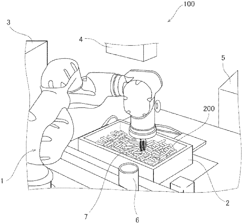
[0035] First, refer to figure 1 The overall configuration of the robot system 100 according to the first embodiment will be described.

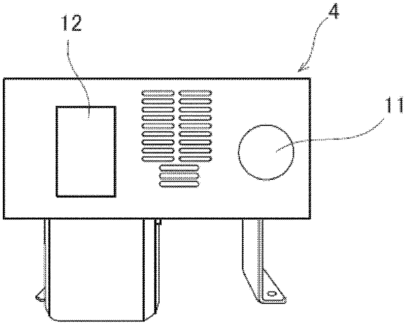
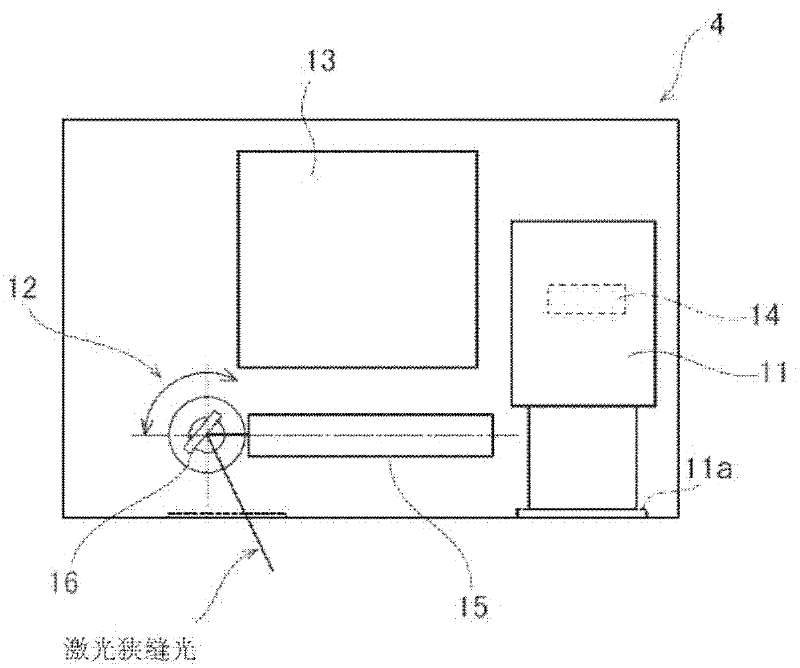
[0036] Such as figure 1 As shown, the robot system 100 is provided with: a robot 1; a stocker 2; a robot controller 3; a sensor unit (distance image sensor unit) 4; a user controller 5; In addition, the sensor unit 4 is an example of a "shape measuring device".

[0037] The stocker 2 is constituted by a box (tray) formed of resin or the like, and a plurality of workpieces 200 such as bolts, for example, are placed inside the stocker 2 . The robot 1 is a vertical articulated robot, and a hand device 7 for grasping the workpieces 200 placed in the stocker 2 one by one is provided on the top of the robot 1 . In addition, the hand device 7 is an example of a "grip". In addition, the workpiece 200 grasped by the hand device 7 is configured as follows, and is moved to the conveyance pallet 6 for conveying the workpiece 200 to the next process. ...

no. 2 Embodiment approach

[0076] Below, refer to Figure 14 and Figure 15 The robot system 101 of the second embodiment will be described. In this second embodiment, unlike the first embodiment in which the workpiece 200 is directly placed on the surface 20 , the workpiece 200 is placed on the box-shaped pallet 102 .

[0077] Such as Figure 14 and Figure 15 As shown, in the robot system 101 of the second embodiment, a plurality of workpieces 200 are placed on a box-shaped pallet 102 . In addition, other configurations of the second embodiment are the same as those of the above-mentioned first embodiment.

[0078] Below, refer to Figure 14 to Figure 20 The operation of the three-dimensional measurement by the sensor controller 13 of the second embodiment will be described.

[0079] First, before measuring the workpiece 200 three-dimensionally, as Figure 16 and Figure 17 As shown, in the state where the workpiece 200 is not placed on the tray 102, the tray 102, the surface 103 on which the ...


PUM


Abstract

A shape measuring system includes a laser emitter that emits a laser beam, a scanner that scans the laser beam emitted by the laser emitter over a region in which an object is placed, a camera that detects reflected light of the laser beam, a recognizer that performs three-dimensional measurement of the object on the basis of the detection result of the camera, and a controller that performs control so as to change a scanning range of the scanner in accordance with the region in which the object is placed, the region being detected by the camera.

Description

technical field [0001] The disclosed embodiments relate to a shape measurement device, a robot system, and a shape measurement method. Background technique [0002] Japanese Patent Application Laid-Open No. 2001-277167 discloses a shape measurement device (3-dimensional posture recognition method) provided with a laser irradiation unit that irradiates laser light. [0003] The shape measurement device (3D posture recognition method) is equipped with: a laser device (laser irradiation unit) that irradiates line laser light (laser); and a CCD camera that is irradiated by the laser device and is irradiated by the component group (measurement object) Reflected reflected light. In this 3D gesture recognition method, a laser device is configured to irradiate line laser light while moving from a predetermined start position to an end position on a component group, and the component group is calculated from the reflected light from the component group received by a CCD camera. the...

Claims


Application Information

Patent Timeline
IPC IPC(8): B25J13/08B25J19/02B25J9/00
CPCG01B11/2518
Inventor 半田博幸有江健
Owner YASKAWA DENKI KK
Why Eureka
Try Eureka