
Hydraulic former for plain film-coated building circular template

A technology of forming machine and round formwork, applied in the direction of wood compression, etc., can solve the problems of difficult control of product quality and size standards, large influence of human factors of round formwork, poor surface flatness of finished products, etc., so as to improve product quality and reduce construction costs. , the effect of good flatness

Active Publication Date: 2012-07-04
廊坊兴山木业有限公司
View PDF8 Cites 6 Cited by
  • Summary
  • Abstract
  • Description
  • Claims
  • Application Information

AI Technical Summary

Problems solved by technology

[0003] At present, the processing of clear water-coated building round formwork is mainly completed by manual operation. The operator rolls up the plate to be processed and fixes it on the lifting punch, and binds the plate through the uniformly distributed fixing brackets on the punch to make the plate close. The punch, the punch has a higher temperature, and the plate is deformed into the required semicircle template by the action of mechanical force and high temperature. The current processing method mainly has the following defects: 1. It requires more labor and lower production efficiency; 2. 1. The artificially produced round formwork is greatly affected by human factors, and it is easy to produce waste products if it is operated carelessly; 3. It is difficult to control the product quality and size standards. The formed round formwork will rebound to varying degrees, and the surface of the finished product is flat Poor; 4. Since the size of the round formwork is not uniform, it needs to be adjusted during installation, which requires high technical requirements for later installation and lower installation efficiency

Method used


Image

  • Hydraulic former for plain film-coated building circular template
  • Hydraulic former for plain film-coated building circular template
  • Hydraulic former for plain film-coated building circular template

Examples

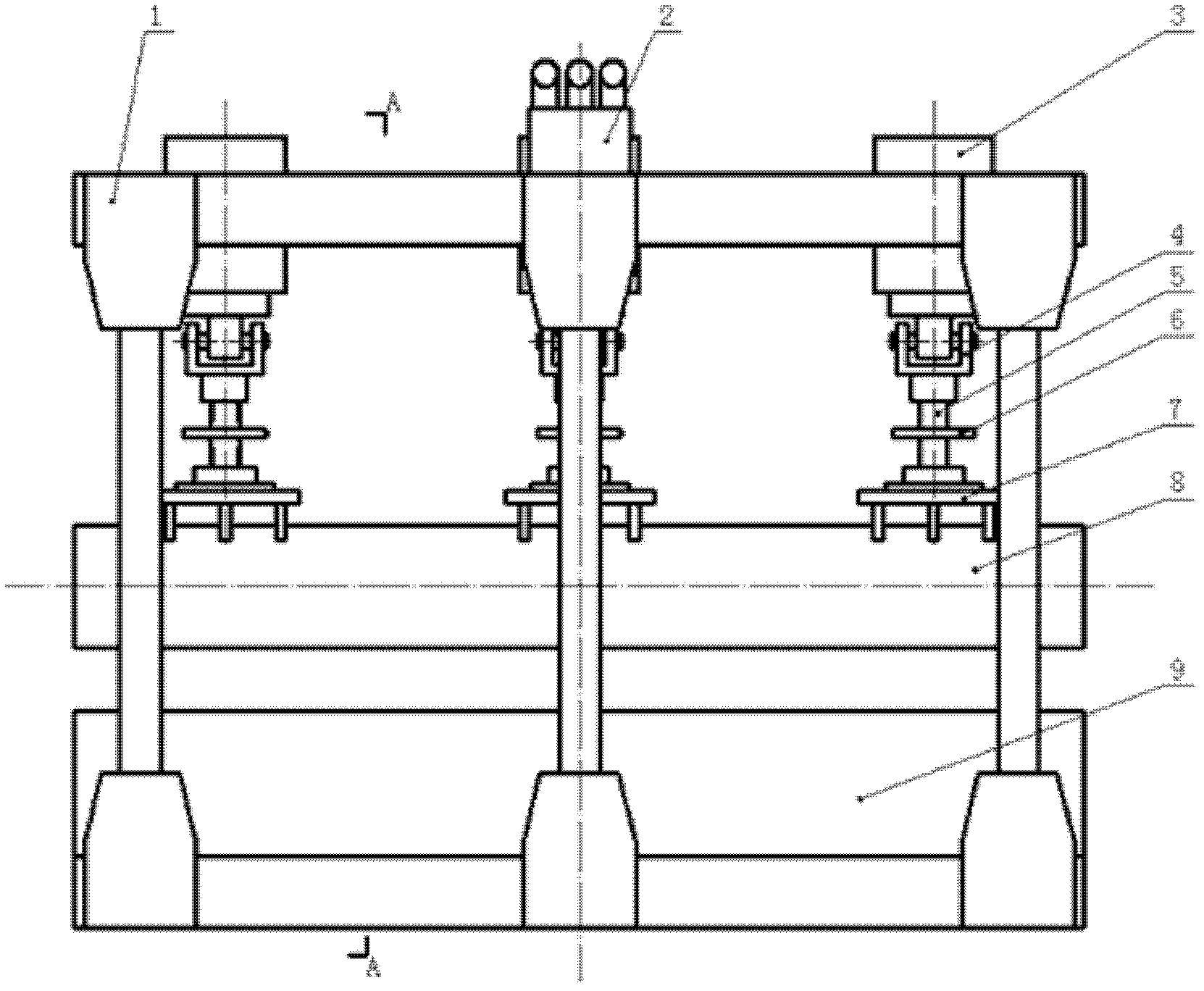
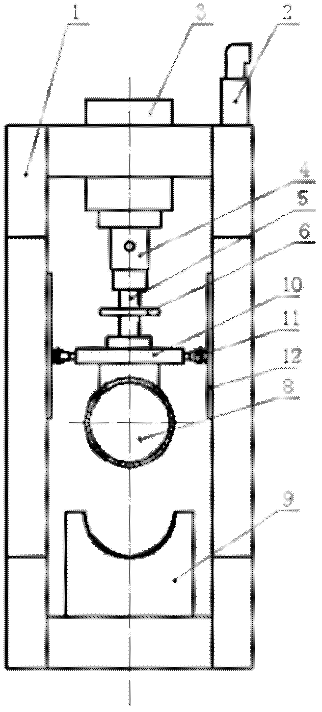
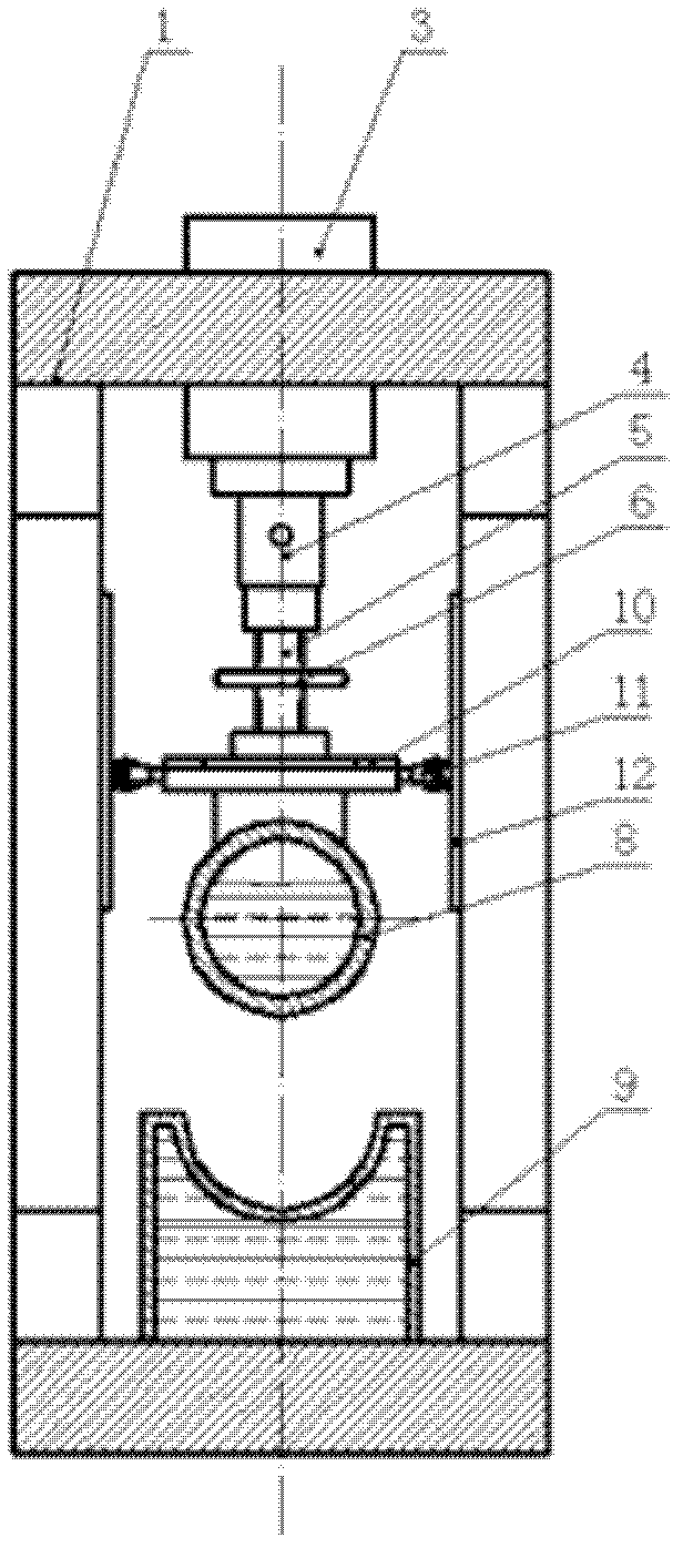

Embodiment Construction

[0026] The present invention will be further described in detail below in conjunction with the accompanying drawings and through specific embodiments. The following embodiments are only descriptive, not restrictive, and cannot limit the protection scope of the present invention.

[0027] A hydraulic forming machine for clear water film-coated building circular formwork, comprising a square frame frame 1, a hydraulic cylinder 3 is installed at the upper end of the frame, a punch 8 is installed at the lower end of the hydraulic cylinder in the frame, and a punch 8 is installed at the lower end of the frame corresponding to the punch There is a concave mold 9 fixedly installed, both the convex mold and the concave mold have a hollow structure, and there is a hot liquid medium inside, through the continuous high temperature convex mold and concave mold, the processing and forming effect is improved, and the rebound of the round template after forming is avoided, and the product qual...


PUM


Abstract

The invention relates to a hydraulic former for a plain film-coated building circular template, which comprises a square frame type machine frame. A hydraulic cylinder is installed at the upper end of the frame; a convex mold is installed at the lower end of the hydraulic cylinder in the frame; a concave mold is fixedly installed at the lower end of the machine frame corresponding to the convex mold; and both the convex mold and the concave mold are of hollow structures and are full of hot liquid media. The invention has the beneficial effects that by adopting the hydraulic transmission control, automatic production is realized; the hydraulic former has the advantages of scientific and reasonable design, easiness for processing and convenience in operation, the production efficiency is effectively improved, the labor is saved, and the labor intensity of operators is reduced; and moreover, the produced circular template is high in standardization degree and good in quality and is not required to be adjusted again when being installed by a constructor, so that the later construction is facilitated, and the construction cost can be reduced.

Description

technical field [0001] The invention belongs to the field of construction, and relates to concrete formwork processing equipment, in particular to a hydraulic forming machine for clear water-covered building round formwork. Background technique [0002] With the emergence of innovative technology clear water film-coated building formwork, the traditional steel formwork is gradually replaced by clear water film-coated building formwork. Such as the Chinese patent "a kind of clear water film-covered building circular formwork" (CN201027381), which is assembled into a cylindrical formwork by two wooden semicircular formworks, and a fastening hoop is installed outside the cylindrical formwork; The inner and outer surfaces of the semicircular template are covered with a phenolic resin film layer. In order to avoid the leakage of concrete and the problem of grout running out after beating, it is necessary to connect the two semicircular formwork with buckles, and the connection p...

Claims


Application Information

Patent Timeline
Patent Type & Authority Applications(China)
IPC IPC(8): B27M1/02
Inventor 李正国
Owner 廊坊兴山木业有限公司
Learn More