Automatic ink feeding writing brush
An automatic and writing brush technology, applied to other ink pens, printing, writing utensils, etc., can solve the problems of using together, it is difficult to use pens, and the works are not listed, etc., to achieve the effect of good fixation and not easy to fall off
- Summary
- Abstract
- Description
- Claims
- Application Information
AI Technical Summary
Problems solved by technology
Method used
Image
Examples
Embodiment 1
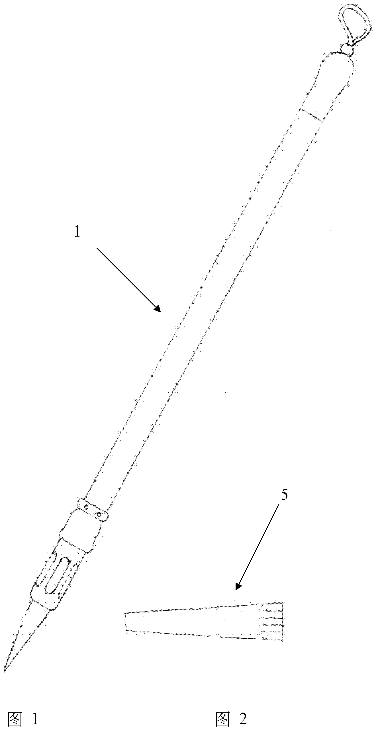
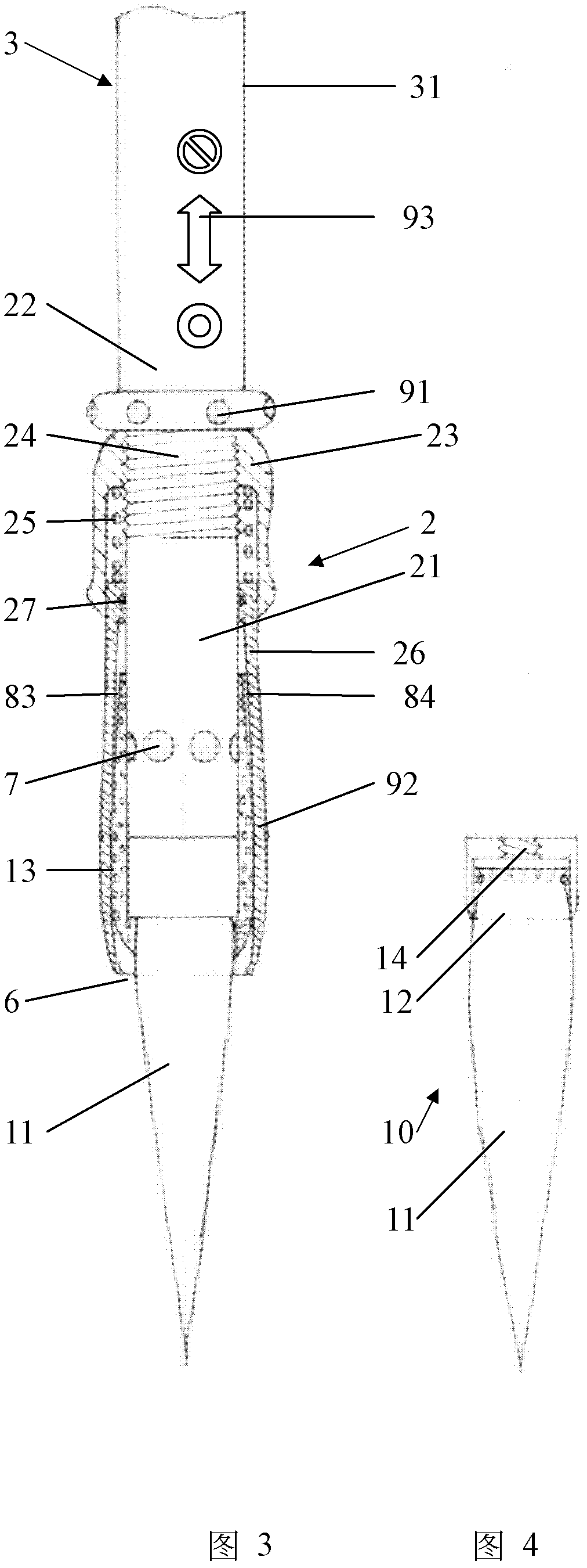
[0060] see figure 1 and figure 2 According to the first embodiment of the automatic ink supply writing brush 1 of the present invention, the appearance and volume of the automatic ink supply writing brush 1 are basically the same as those of traditional writing brushes, and the feel and writing style of holding the pen during writing are consistent with traditional writing brushes. see image 3 , Figure 4 , Figure 5 , the automatic ink supply writing brush 1 is composed of a nib assembly 10, a pen holder assembly 2 and a pen holder assembly 3, etc., and the ink liquid 4 can be injected into the pen holder assembly 3. The pen bucket assembly 2 is detachably connected with the nib assembly 10 and the pen holder assembly 3 .
[0061] see image 3 , the pen bucket assembly 2 is composed of a pen bucket seat 21, a pressure regulating sleeve 23, a spring 25, a rotating jacket 26, a sealing ring 27, an ink absorbing body 13, etc., the pen bucket seat 21 is a sleeve with a fla...
Embodiment 2
[0090] see Figure 12 , the second embodiment of the present invention and Figure 6 The structural basis of the first embodiment shown is the same, the main difference is that the bottom of the pen holder in this embodiment is connected with the connecting bolt 236 at the bottom of the valve core of the rectifying plunger valve 235 through the connecting thread 228 of the pen holder, and the bottom of the pen holder in this embodiment The inner casing 32 of the pen bucket does not have a side passage. This structure is beneficial for smaller diameter pen applications.
[0091] Figure 13 yes Figure 12 Schematic diagram of the switching variation of the illustrated embodiment. The left side of the axis in the figure is the open state of the fluid channel. At this time, the inner casing 32 of the pen bucket is pulled up, so that the side channel 74 of the pen bucket seat communicates with the inner cavity of the inner sleeve 32 of the pen bucket; the right side of the axis...
Embodiment 3
[0093] see Figure 14 , the lower sectional view of the third embodiment of the present invention. The structure of this embodiment is relatively simple, and Figure 6 The principle basis of the shown first kind of embodiment is the same, adopts the nib that directly embeds the traditional craft to make equally, adopts to replace the pen holder to load ink with relative maximum capacity. The fluid passes through the side channel, the ink in the cavity is transferred to the nib by the ink absorber, and the air enters the cavity through the air inlet through the ink absorber. Flow control is all done with valves and rotary jackets. The difference lies in the way the components are connected and sealed.
[0094] This embodiment includes a pen holder body 331, a pen holder 321 and a pen holder inner sleeve 332, the pen holder body 331 has an ink chamber 341, the pen holder body 331 is equivalent in diameter to the pen holder inner sleeve 332, and the pen holder 321 has a pen ...
PUM
 Abstract
Description
Claims
Application Information
 - R&D
- Intellectual Property
- Life Sciences
- Materials
- Tech Scout
- Unparalleled Data Quality
- Higher Quality Content
- 60% Fewer Hallucinations
Browse by: Latest US Patents, China's latest patents, Technical Efficacy Thesaurus, Application Domain, Technology Topic, Popular Technical Reports.
© 2025 PatSnap. All rights reserved.Legal|Privacy policy|Modern Slavery Act Transparency Statement|Sitemap|About US| Contact US: help@patsnap.com


