Automobile warm air control method and automobile warm air control device

The technology of a heating device and a control method is applied to the heating control of heating. , Demisting in the cockpit of electric vehicles, method and device for heating air control in automobiles, and defrosting field, which can solve the problems of expensive high-power relays, poor temperature control smoothness, softening of surrounding plastics, etc., to avoid excessive surface temperature and maintain Consistency and stability, the effect of increasing reliability

Inactive Publication Date: 2012-07-04
NEW ENERGY AUTOMOBILE BRANCH FAW GROUP CORP
View PDF6 Cites 32 Cited by
  • Summary
  • Abstract
  • Description
  • Claims
  • Application Information

AI Technical Summary

Problems solved by technology

[0007] The invention discloses a method and device for controlling the warm air of an automobile, in order to solve the hidden danger that the simple PTC heating under the high voltage above 300V in the prior art may easily cause the surrounding plastics to soften or even burn
[0008] The present invention also provides a control device for realizing the above method. Each group of PTCs realizes the adjustment of PTC power through the switch of the high-voltage relay, which overcomes the stepless adjustment of power without power in the prior art, and the smoothness of temperature control is not good, and it is easy to cause overheating or overheating. Cold; high-power relays are expensive, resulting in high overall cost and other issues

Method used


Image

  • Automobile warm air control method and automobile warm air control device
  • Automobile warm air control method and automobile warm air control device
  • Automobile warm air control method and automobile warm air control device

Examples


Embodiment Construction

[0026] An embodiment of the present invention will be described in detail below in conjunction with the accompanying drawings.

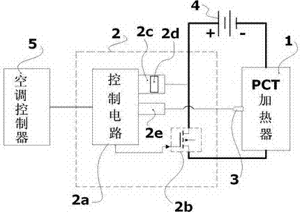
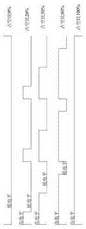
[0027] Such as figure 1 , image 3 As shown, the automobile warm air control method of the present invention includes the following steps: PTC heater 1 is loaded with strong electric voltage; 1 The temperature is compared with the target temperature value; the control circuit 2a detects the voltage and current of the strong current circuit of the PTC heater 1 through the photoelectric coupling strong and weak current isolation circuit 2d; it is characterized in that: the driving circuit 2b uses an edge-gate bipolar transistor (IGBT), Receive the duty cycle pulse width modulation signal output by the control circuit 2a to turn on or off the collector and emitter; the strong power supply 4 is applied to the PTC heater 1 through the drive circuit 2b insulated gate bipolar transistor (IGBT).

[0028] The drive circuit 2b insulated gate bipolar transist...


PUM


Abstract

The invention discloses an automobile warm air control method and an automobile warm air control device. The method includes steps: using a control circuit to load weak-current voltage; using a PTC (positive temperature coefficient) heater to load strong-current voltage; using the control circuit to detect temperature of the PTC heater and comparing the temperature of the PTC heater with a target temperature value; and using the control circuit to detect the voltage and the current of a strong-current circuit of the PTC heater through a photocoupling strong-weak current isolation circuit. The automobile warm air control method and the automobile warm air control device are characterized in that a driving circuit receives duty cycle pulse width modulation signals outputted by the control circuit by the aid of an IGBT (insulated gate bipolar transistor) to lead a collector and an emitter to be on or off; and a strong-current power source is applied to the PTC heater through the IGBT. Strong-current voltage of different frequencies is outputted under pulse width modulation control and duty cycle change to realize linear control of the PTC heater. The automobile warm air control method and the automobile warm air control device have the advantages that overhigh surface temperature of the PTC heater can be effectively avoided so that reliability is high and risks and potential hazards are avoided; electrodeless power adjustment and smooth temperature control are realized, and overheating and overcooling are avoided; and cost is low.

Description

technical field [0001] The invention belongs to the technical field of automobile temperature adjustment equipment, and relates to an automobile warm air control method and device; it is especially suitable for defogging, defrosting, and heating warm air control in the cockpit of an electric vehicle. Background technique [0002] Traditional passenger cars use engine cooling water circulation to heat the cockpit for heating, defogging, and defrosting in winter, while pure electric vehicles do not use traditional engines as power sources, so engine cooling water cannot be used for circulating heating and defrosting. Fog, defrosting; therefore, the heating, defogging, and defrosting of the vehicle need to rely on other technical means to achieve. [0003] Known existing solutions for electric vehicles include PTC heaters and temperature sensors; the PTC heater element works under a strong electric voltage above 300V; the hot air output pipe of the PTC heater is connected to th...

Claims


Application Information

Patent Timeline
Patent Type & Authority Applications(China)
IPC IPC(8): B60H1/22B60R16/02B60S1/54
Inventor 胡成台陈燕洲王德平于春涛
Owner NEW ENERGY AUTOMOBILE BRANCH FAW GROUP CORP
Why Eureka
Try Eureka