
Thrust wheel for heavy-duty railway wagons and bogie thereof

A technology of supporting rollers and bogies, which is applied in the direction of the relative movement of railway car body parts, chassis and bogies in the direction of device, transportation and packaging, etc., which can solve the difficulty of connecting other vehicles and locomotives, and the unfavorable combination of supporting facilities Application, can not effectively reduce the unsprung quality and other problems, to achieve the effect of low manufacturing difficulty, simple structure and low cost

Active Publication Date: 2012-07-04
张二群
View PDF9 Cites 5 Cited by
  • Summary
  • Abstract
  • Description
  • Claims
  • Application Information

AI Technical Summary

Problems solved by technology

[0004] Although traditional multi-axle bogies, such as four-axle and eight-wheel bogies, can also greatly increase the load capacity and disperse the wheel-rail contact stress, a connecting beam must be added to connect the two sets of bogies into a structure, so the center point of roll It will inevitably rise, and it is not conducive to the combined application of loading, unloading, and supporting facilities such as station equipment conditions, and it also causes difficulties in connecting other vehicles and locomotives; at the same time, the traditional multi-axle bogie has a complex structure, high manufacturing cost, and heavy weight. The mass is large, and it cannot effectively reduce the unsprung mass and improve the running quality, so it is not an ideal choice for heavy-duty transportation

Method used


Image

  • Thrust wheel for heavy-duty railway wagons and bogie thereof
  • Thrust wheel for heavy-duty railway wagons and bogie thereof
  • Thrust wheel for heavy-duty railway wagons and bogie thereof

Examples


Embodiment Construction

[0028] A track wheel and bogie for a heavy-duty railway vehicle according to a preferred embodiment of the present invention will be described below with reference to related drawings, wherein the same components will be described with the same reference numerals.

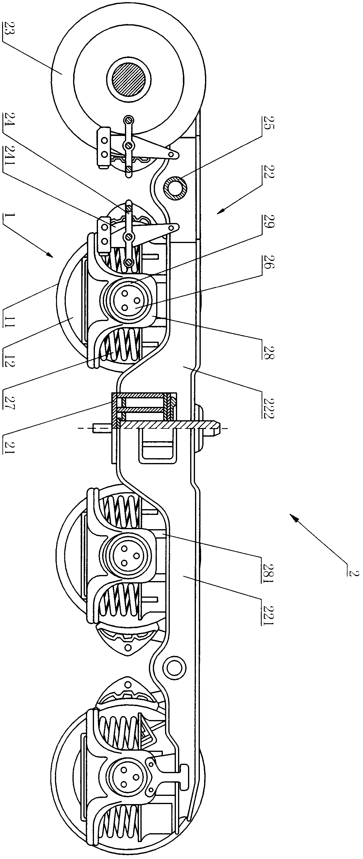
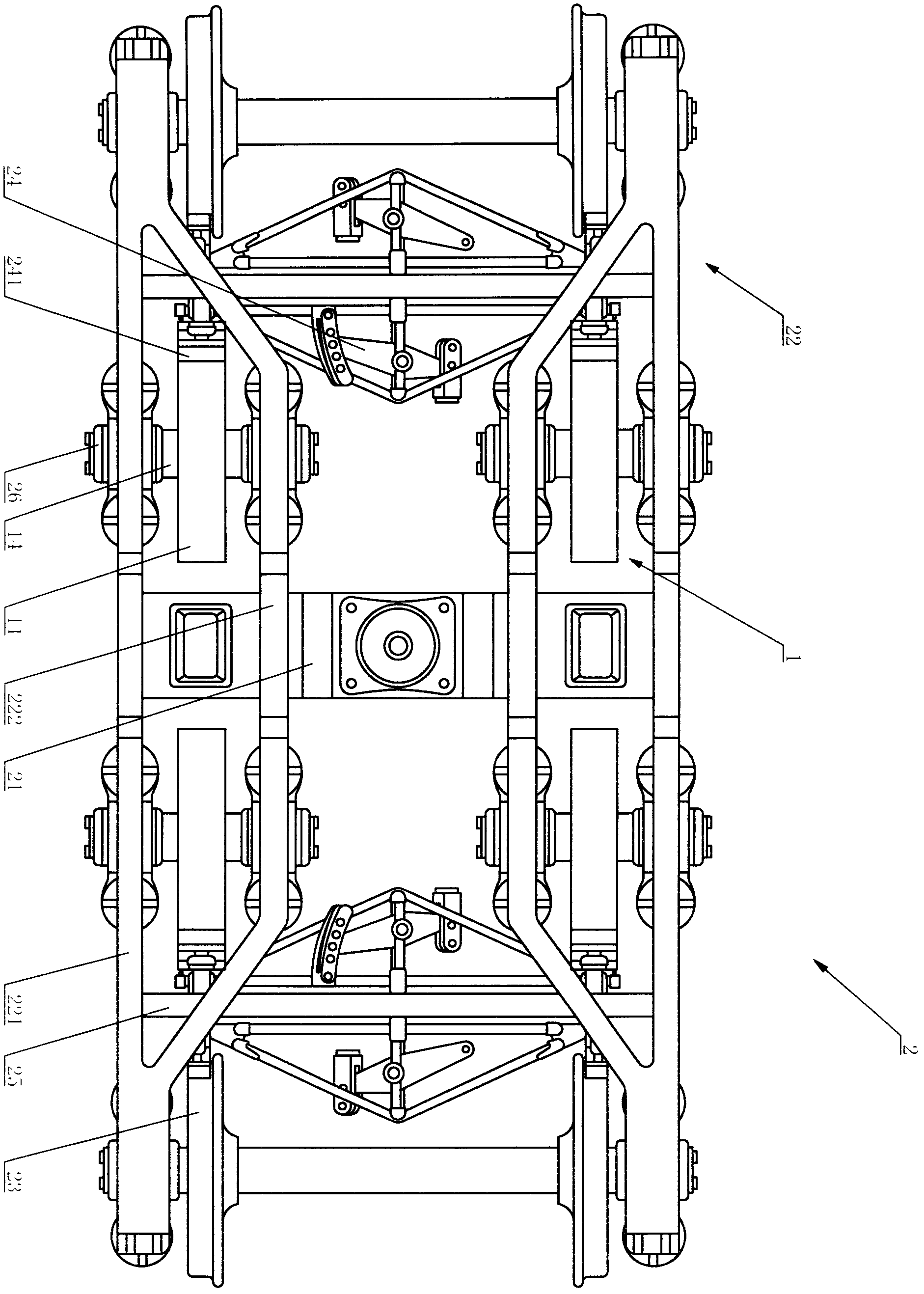
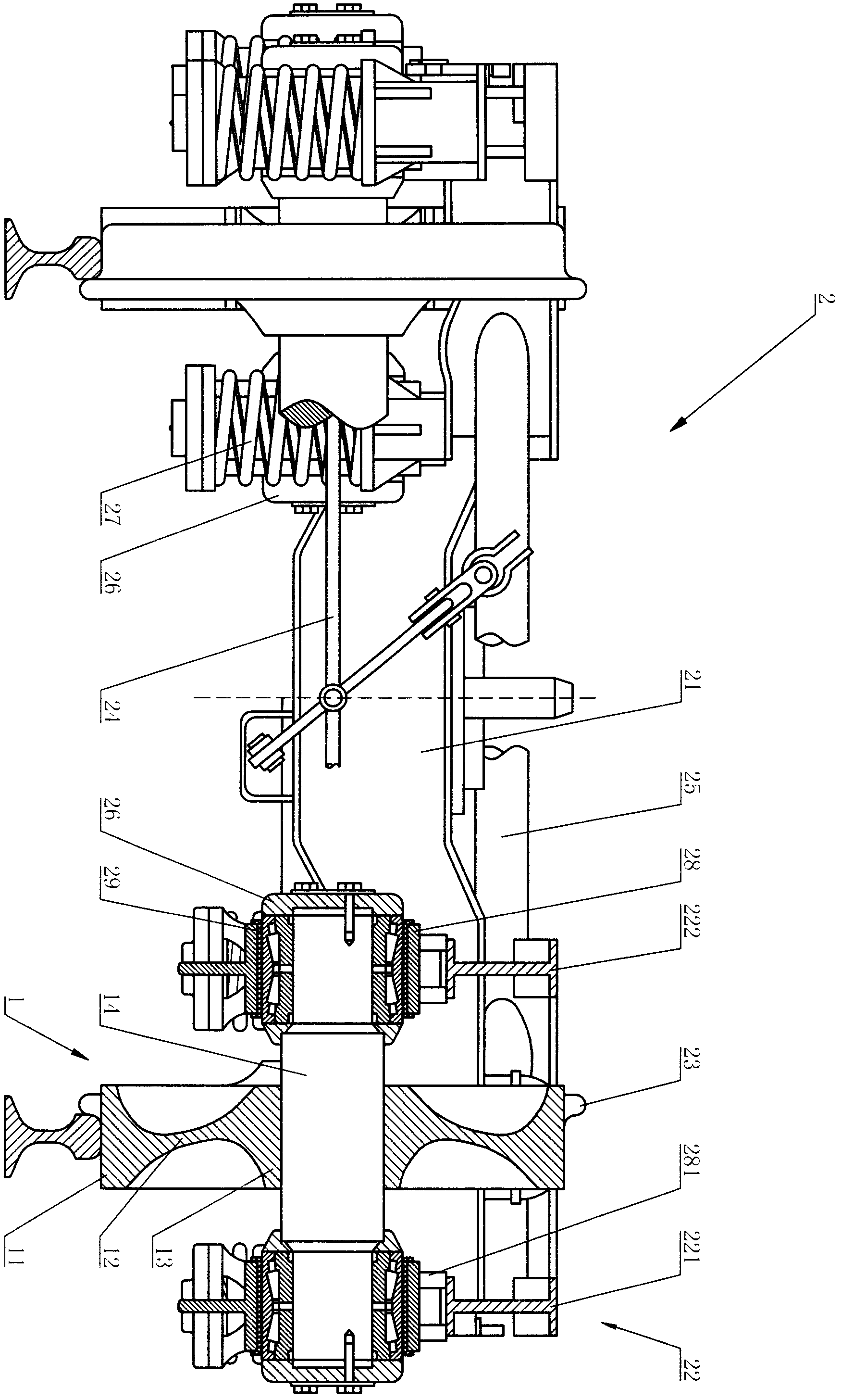
[0029] refer to figure 1 As shown, a bogie 2 of a railway heavy-duty truck vehicle in a preferred embodiment of the present invention includes a central beam 21, side frames 22 symmetrically connected to the two ends of the central beam 21, and symmetrically arranged on both sides of the side frames through the wheels. The wheel pair 23 at the end also includes at least one pair of track wheels 1 located between the wheel sets 23, the track wheels 1 are arranged on the side frames 23, and the track wheels 1 are as follows.

[0030] Also refer to figure 2 , image 3 As shown, the supporting wheel 1 includes an integrated rim 11, web 12 and hub 13; no rim is provided on the outer wheel surface of the rim 11, the w...


PUM


Abstract

The invention relates to a thrust wheel and a bogie, and in particular relates to a thrust wheel (which is applicable to heavy-duty railway wagons, can reduce loss and unsprung mass, and can reduce the operation cost, improve the quality of operation and greatly increase the carrying capacity) for heavy-duty railway wagons, and a bogie thereof. The bogie comprises a central crossbeam, side frames and wheel sets, wherein the side frames are symmetrically connected to the two ends of the central crossbeam, and the wheel sets are symmetrically arranged at the two ends of each side frame by a wheel set shaft; and the bogie is characterized in that the bogie also comprises at least a pair of thrust wheels arranged between the wheel sets; the thrust wheel is arranged on the side frame and comprises a rim, a radial plate and a hub which are integrally arranged; and the external wheel surface of the rim is not provided with a wheel flange, and the operating surface of the rim is axially horizontal and 115mm in width. The thrust wheel and bogie provided by the invention has the advantages that: the carrying capacity of the bogie is greatly increased, the contact stress to a wheel rail is reduced, the abrasion of the wheel rail is reduced, the quality of operation is improved, and the operating cost is reduced; meanwhile, the bogie is simple in structure, low in manufacturing difficulty, and low in cost.

Description

technical field [0001] The invention relates to a supporting wheel and a bogie, in particular to a supporting wheel and a bogie of a heavy-duty railway vehicle. Background technique [0002] In order to improve the railway transportation capacity, in addition to the management level, speed increase and heavy load are two indispensable technical means. In our country, remarkable achievements have been made in terms of train speed, especially in passenger transport, and great progress has been made in freight transport, but there is still much work to be done. At present, the axle load of my country's railway freight cars has also increased to 23t, and the coal train has reached 25t. Except for special vehicles such as large-tonnage clamp cars and flat cars with concave bottoms, the load of each section of general freight vehicles is borne by two two-axle bogies. , or increase the number of axles of the bogie to form a multi-axle bogie; or increase the bearing capacity of th...

Claims


Application Information

Patent Timeline
Patent Type & Authority Applications(China)
IPC IPC(8): B61F5/02B61F13/00
Inventor 张二群
Owner 张二群
Learn More