
Automatic machine oil cleaning system, oil return pipeline of communicating vessel, and engine system

An engine system and oil return pipeline technology, which is applied in the installation/connection of lubricant conduit devices, lubricant purification devices, and lubricating parts, etc., can solve the problems of low reliability, structural limitations of oil pans, and complex structures, etc. Achieve the effect of prolonged replacement cycle, low cost and increased cleanliness

Active Publication Date: 2012-07-04
HUAWEI TECH CO LTD
View PDF8 Cites 17 Cited by
  • Summary
  • Abstract
  • Description
  • Claims
  • Application Information

AI Technical Summary

Problems solved by technology

However, the current automatic oil cleaning system has a complex structure, low reliability, and limits the structure of the oil pan

Method used


Image

  • Automatic machine oil cleaning system, oil return pipeline of communicating vessel, and engine system
  • Automatic machine oil cleaning system, oil return pipeline of communicating vessel, and engine system
  • Automatic machine oil cleaning system, oil return pipeline of communicating vessel, and engine system

Examples


Embodiment 1

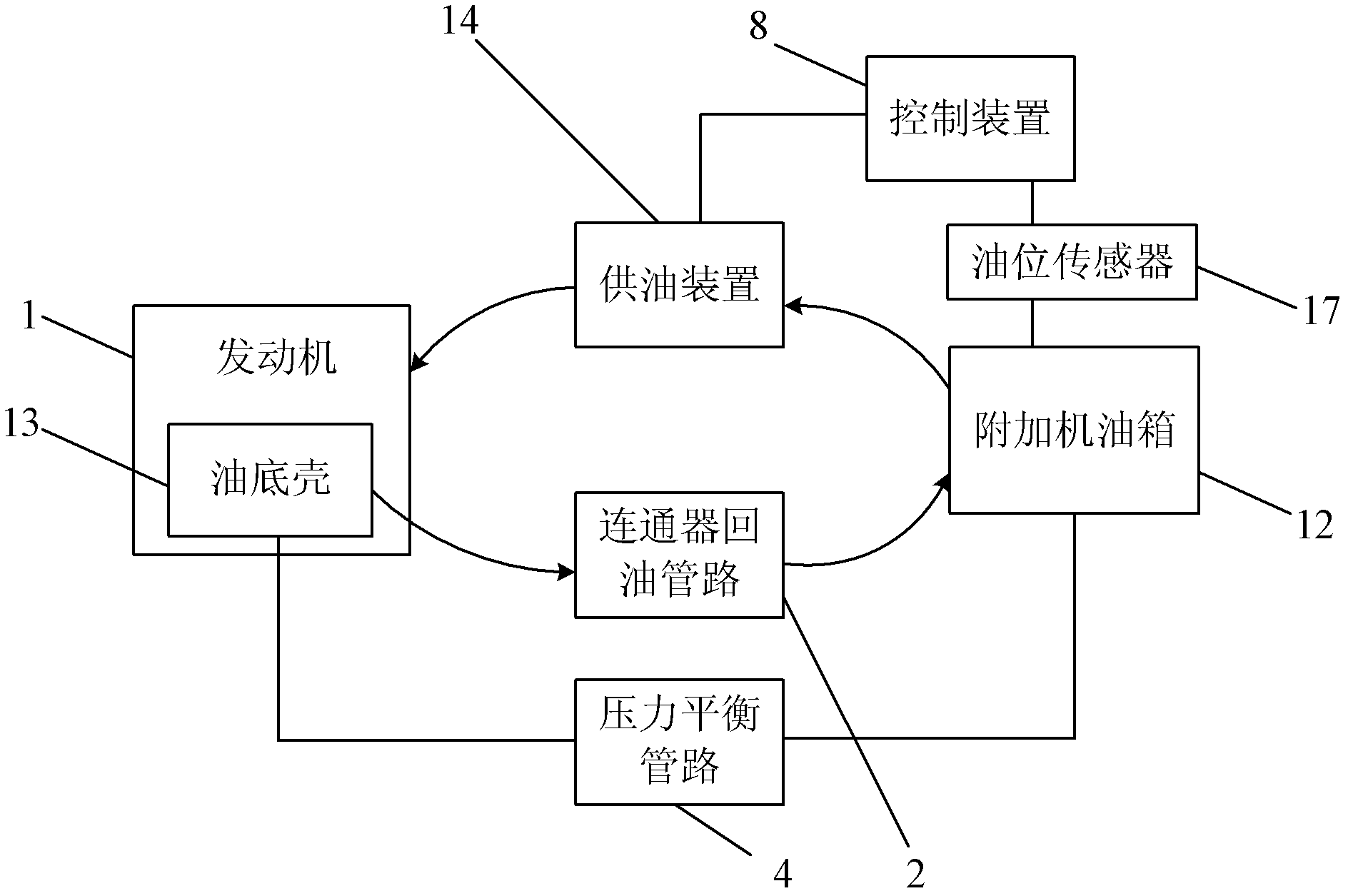
[0025] An embodiment of the present invention provides an automatic engine oil cleaning system, such as figure 1 As shown, the system includes:

[0026] Additional engine oil tank 12, is used for storing engine oil;

[0027] An oil supply device 14 communicated with the additional oil tank 12 and the engine 1 respectively, for extracting and filtering the oil in the additional oil tank 12 and then injecting it into the engine 1;

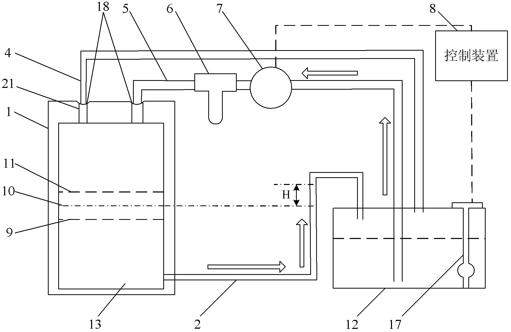
[0028] Connector oil return pipeline 2, the two ends of the connector oil return pipeline 2 respectively communicate with the bottom end of the oil pan 13 and the top end of the additional oil tank 12, the highest of the connector oil return pipeline 2 The height at the point is higher than the engine oil level height set in the oil pan 13 and has a height difference, and the engine oil level height set in the oil pan 13 is located at the maximum and minimum engine oil levels allowed by the engine Between the heights, the height difference is set a...


PUM


Abstract

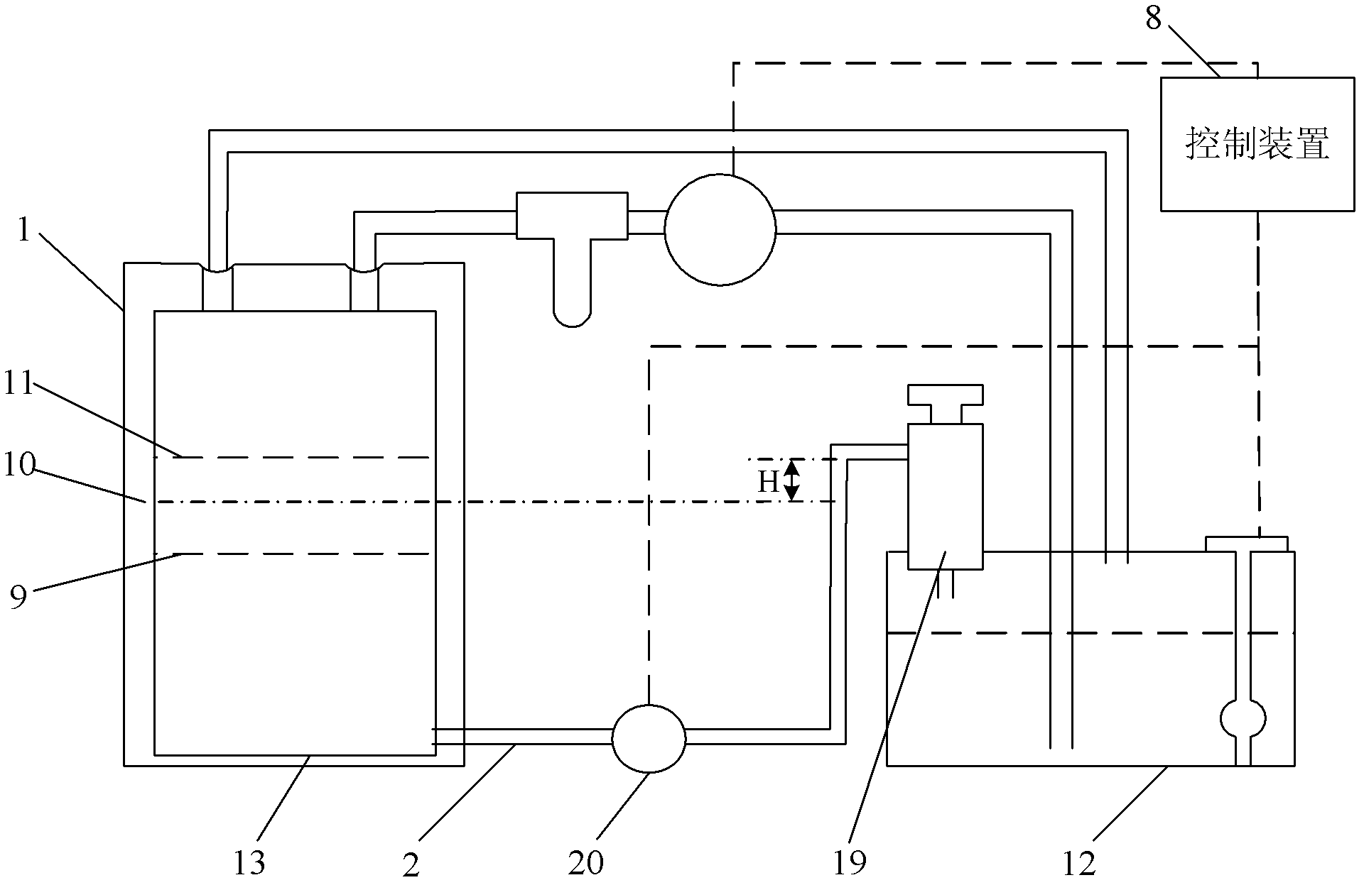
The embodiment of the invention provides an automatic machine oil cleaning system, relates to the technical field of internal combustion engines lubrication, and is used for prolonging the replacing period of machine oil in an engine, reducing the cost of a machine oil cleaning system, and improving the reliability of the machine oil cleaning system. The automatic machine oil cleaning system comprises an auxiliary machine oil box, an oil supply device connected with the auxiliary machine oil box and the engine respectively, and an oil return pipeline of a communicating vessel, wherein two ends of the oil return pipeline are communicated with the bottom end of an oil pan and the top end of the auxiliary machine oil box respectively; the peak of the oil return pipeline is higher than the set machine oil level of the oil pan; the set machine oil level of the oil pan is lower than the accessible uppermost level and the accessible bottommost level of the engine; the height difference between the set machine oil level of the oil pan and the accessible uppermost level or the accessible bottommost level is set according to the pressure in the oil pan during the operation of the engine and the atmospheric pressure, so that when the machine oil level in the oil pan is higher than the set machine oil level, machine oil can flow back to the auxiliary machine oil box along the oil return pipeline.

Description

technical field [0001] The invention relates to the technical field of internal combustion engine lubrication, in particular to an automatic engine oil cleaning system, an oil return pipeline of a connector thereof and an engine system. Background technique [0002] Engine oil, that is, engine lubricating oil, can lubricate, clean, cool, seal, and reduce wear on the engine. The engine oil will consume a certain amount during the operation of the engine, and metal wear debris, dust, carbon deposits and colloidal deposits oxidized at high temperature, water, etc. in the engine will continue to be mixed into the engine oil, so the engine needs regular maintenance , replace the engine oil, clean or replace the oil filter, how to extend the maintenance interval of the engine oil, and reduce maintenance costs have always been a major issue to be solved urgently in the relevant industries. [0003] In order to extend the service life of the engine oil, the existing engine oil auto...

Claims


Application Information

Patent Timeline
IPC IPC(8): F01M11/03F01M11/12F01M11/02
Inventor 刘京
Owner HUAWEI TECH CO LTD
Learn More