
Rotary engine with double rows of pistons

A rotary engine and piston-type technology, applied in the field of power machinery, can solve problems such as high manufacturing cost, reduced air chamber sealing, pollution, etc., and achieve the effects of increasing work reliability, eliminating mechanical vibration, and reducing manufacturing costs

Inactive Publication Date: 2012-07-04
方保林
View PDF5 Cites 6 Cited by
  • Summary
  • Abstract
  • Description
  • Claims
  • Application Information

AI Technical Summary

Problems solved by technology

But it has been unable to replace the traditional crank-connecting-rod-piston machine, which is caused by serious defects caused by its own structure.
First of all, it requires high processing technology and high manufacturing cost.
The second is high fuel consumption, low thermal efficiency, and poor power performance. The third is poor sealing, small pressure ratio, insufficient combustion, poor emission performance, and serious pollution.
The fourth is that it is only suitable for high-speed occasions such as light-duty and low-power racing cars and motorcycles. When the speed is slow and idling, the sealing between the air chambers will decrease, and the air leakage and smoke will be serious; the fifth is that it can only be used as a gasoline engine with a small pressure ratio. compression ignition diesel engine

Method used


Image

  • Rotary engine with double rows of pistons
  • Rotary engine with double rows of pistons
  • Rotary engine with double rows of pistons

Examples


Embodiment Construction

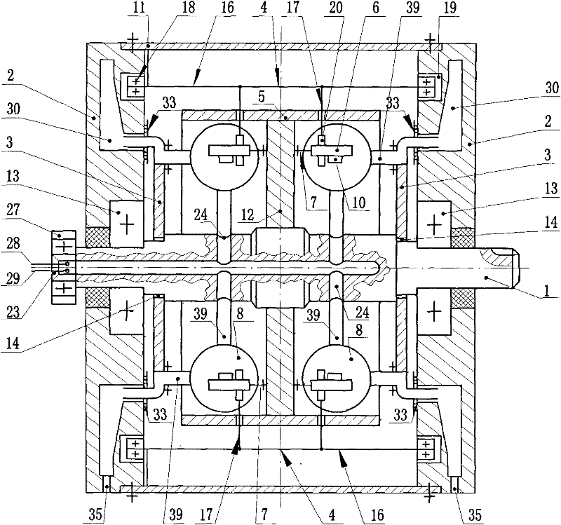
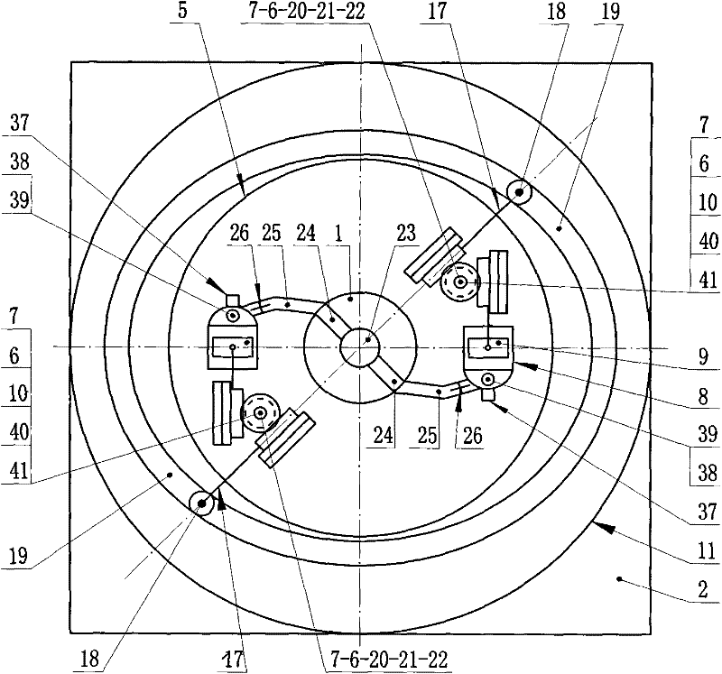
[0028] Because this model is a double-row symmetrical structure, the crank-connecting rod piston type single-cylinder engine head (8) and its corresponding supporting parts are fixedly installed on the two sides of the head tray (12) and are in one-to-one correspondence with each other. Back-to-back, the two parallel vertical bars (17) of the double T-shaped rolling link (3) are respectively connected with the transmission parts on both sides at the same time, and the two vertical bars (17) are connected to the double T-shaped rolling link (3). Driven by it, its movement is synchronous and its direction is exactly the same. For ease of description, simple and clear, only one side of the pallet (12) is described below for the single-row head movement and work process, and the model is further described in detail below in conjunction with the description of the drawings and specific implementation methods: design elliptical track groove (major axis- Minor axis)÷2=piston stroke S...


PUM


Abstract

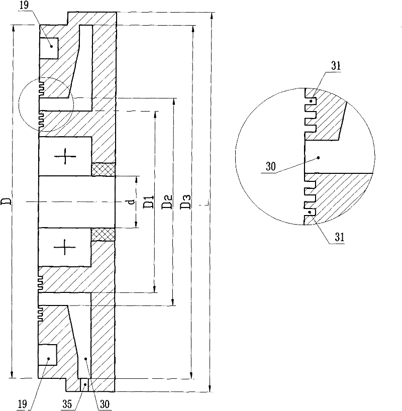
A rotary engine with double rows of pistons belongs to the field of power machinery and consists of a spindle (1), two symmetrical opposite elliptical track groove discs (2), two symmetrical air exhaust double-layered sleeves (3), double-T-shaped rolling connecting rods (4), a bidirectional cylindrical rotating cylinder (5), turning gears (6), gear shafts (7), crank connecting rod piston type single-cylinder engine heads (8), pistons (9), piston rod racks (10), a cylindrical shell (11) and the like. Two or four or a plurality of even-number engine heads (8) are respectively symmetrically mounted on two side surfaces of an engine head tray (12) around centers of the two side surfaces, so that a rotary engine head assembly with double rows of pistons is formed; two rolling connecting rod bearings (18) are inserted into two symmetrical opposite elliptical track grooves (19); and the two piston rod racks (10) and two vertical rod racks (20) are respectively meshed with the two turning gears. The rotary engine is simple and compact in structure, long in service life, stable in running and low in vibration and noise, is high-efficiency, energy-saving and emission-reduction, not only can be made into a gasoline engine, but also can be made into a diesel engine, and is applicable to various types of fuels.

Description

[0001] Technical field: belongs to the field of power machinery. Background technique: [0002] The technical point of the internal combustion engine that is widely used in the world today is a variable capacity mechanism, which can generate enough compression ratio to complete the heat cycle and output torque to do work. The key core technology is the sealing problem between the piston and the cylinder wall in the unit volume, as well as the technical performance indicators such as power, economy and emission. For more than 100 years, the crank-connecting rod piston internal combustion engine, which has been dominant in the engine field, has been very mature. In recent years, the engine has entered the "electronic age", and its development and progress have almost reached the level of "perfect". The mechanism of the rod-piston type has brought the following structural disadvantages that are difficult to overcome: (1) the structure is complex, heavy, and the machining accuracy...

Claims


Application Information

Patent Timeline
Patent Type & Authority Applications(China)
IPC IPC(8): F02B53/02F02B55/08F02B53/04F02B53/10
CPCY02T10/17Y02T10/12
Inventor 方保林
Owner 方保林
Learn More