Engine

A technology for engines and transmission shafts, applied in the direction of machines/engines, mechanical equipment, etc., can solve the problems of low energy conversion efficiency of engines, low energy conversion efficiency, and cannot be further improved, and achieve simple structure, high energy conversion efficiency, and not easy flameout effect

Inactive Publication Date: 2015-08-26
邱华
View PDF4 Cites 1 Cited by
  • Summary
  • Abstract
  • Description
  • Claims
  • Application Information

AI Technical Summary

Problems solved by technology

The piston is doing linear force and the transmission force of the connecting rod, and the angle between the transmission force of the connecting rod and the tangential force of the crankshaft rotation is always changing, resulting in the decomposition of force. Since the component force does not do work, it will cause loss, resulting in The energy conversion efficiency of the engine is low, and the waste of heat energy is huge
At the same time, because the crankshaft rotation radius is limited by the piston displacement distance, piston and connecting rod structure and other conditions, the moment arm of the crankshaft rotation tangential force is limited and cannot be further improved, resulting in low energy conversion efficiency and high energy consumption.

Method used


Image

  • Engine
  • Engine
  • Engine

Examples


Embodiment 1

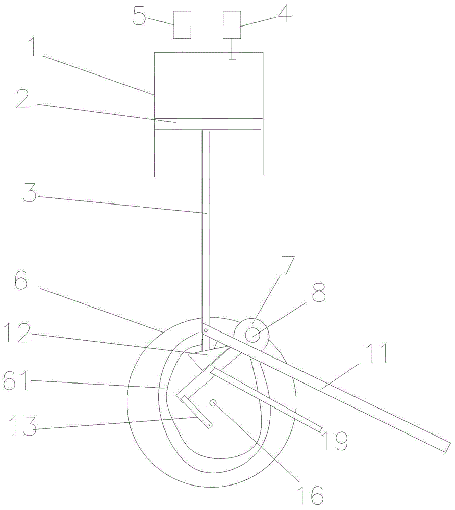
[0027] Such as Figure 1~3 As shown, the engine of the present invention mainly includes a cylinder 1, a piston 2 located in the cylinder 1, a connecting rod 3 connected to the piston 2, an intake device 4, an exhaust device 5, a track mechanism 6 and an elastic mechanism 7 . Among them, the cylinder 1 is provided with an intake valve matched with the intake device 4, and an exhaust valve matched with the exhaust device 5, the intake device 4 provides combustible gas for the cylinder 1, and the exhaust device 5 discharges the combustible gas in the cylinder 1. exhaust gas.

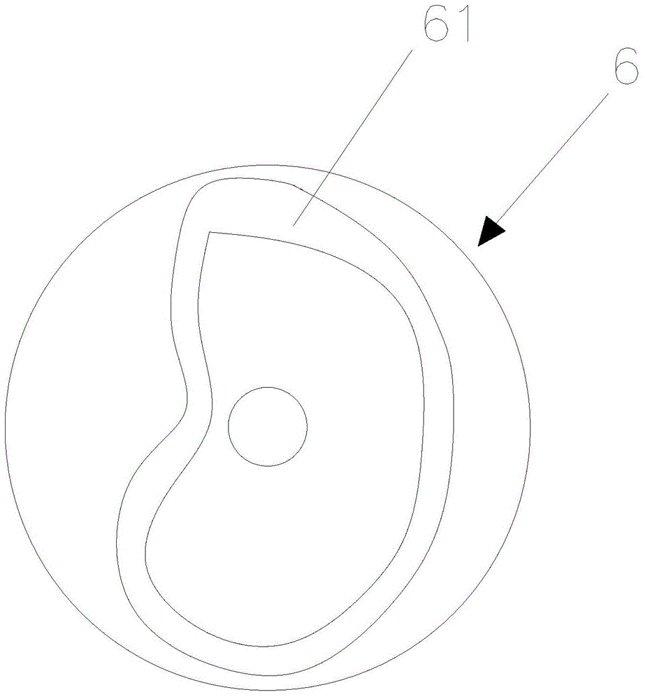
[0028] The track mechanism 6 is in the shape of a turntable, and one side thereof is provided with a closed track 61, and the lower end of the connecting rod 3 is closely matched with the closed track 61. The shape and size of the closed track 61 need to meet the following conditions: the lower end of the connecting rod 3 slides in the closed track 61 for a week to complete the four strokes of air intake...

Embodiment 2

[0036] The track mechanism 6 replaces the turntable shape with a cylindrical shape, and the closed track 61 is arranged on the outer wall of the cylinder, and the cylinder is fixed with a support to make it rotate. Other structural settings are the same as in Embodiment 1.

[0037] Working process of the present invention:

[0038] Intake stroke: the track mechanism 6 drives the connecting rod 3 to move from the top dead center to the bottom dead center, the intake valve opens, the combustible gas is sucked into the cylinder 1, and the intake stroke ends when the piston 2 reaches the bottom dead center. In this process, the switch protrusion 13 locks the elastic mechanism 7, and there is no power output.

[0039]Compression stroke: the track mechanism 6 drives the connecting rod 3 to move from the bottom dead center to the top dead center, the intake valve and the exhaust valve are closed, the combustible gas is compressed, the pressure and temperature rise, until the piston ...


PUM


Abstract

The invention relates to the field of engines. An engine mainly comprises a cylinder, a piston arranged in the cylinder, a connecting rod connected with the piston, an air inlet device and an air exhausting device. The air inlet device provides combustible gas for the cylinder, and the air exhausting device discharges waste gas in the cylinder. The engine further comprises a track mechanism and an elastic mechanism. A closed track is arranged on one side of the track mechanism, the lower end of the connecting rod is tightly matched with the closed track, the track mechanism is matched with the connecting rod to circumferentially rotate, the lower end of the connecting rod slides for one round in the closed track to finish four strokes, the elastic mechanism abuts against the bottom end of the connecting rod and is fixedly connected with a transmission shaft, and the transmission shaft is provided with an output mechanism. The engine is simple in structure, convenient and practical; power can be transmitted more quickly, and accordingly the engine is started easily and is not shut down easily; and the engine is high in compression ratio, saves energy and is high in energy conversion efficiency.

Description

technical field [0001] The invention relates to the field of engines, in particular to an internal combustion engine. Background technique [0002] The current internal combustion engine usually adopts a crank-connecting rod piston engine, which drives the piston by igniting the combustible gas in the cylinder, and then converts the linear motion of the piston into rotary motion through the crankshaft and outputs torque. The crank-connecting rod piston engine is a four-stroke engine. It completes a working cycle through four strokes of intake, compression, power, and exhaust. In this process, the piston reciprocates up and down for four strokes, and the corresponding crankshaft rotates for two weeks. The reciprocating motion of this kind of engine has a large mass. When the engine speed is increased, the inertial force generated by the reciprocating motion increases sharply, forming a great destructive force on the moving parts, and there are defects such as low speed and la...

Claims


Application Information

Patent Timeline
Patent Type & Authority Applications(China)
IPC IPC(8): F02B75/32
Inventor 邱华
Owner 邱华
Why Eureka
Try Eureka