Transmission mechanism and rotary engine thereof

A technology of rotating engines and transmission mechanisms, which is applied in the direction of machines/engines, engine components, combustion engines, etc. It can solve the problems of increased gas blow-by between the mixed gas studios, short service life, and long combustion lines, so as to increase work reliability. , short service life, large emission pollution effect

Inactive Publication Date: 2011-04-27
SHANGHAI MOSES MARINE ENG
View PDF0 Cites 4 Cited by
  • Summary
  • Abstract
  • Description
  • Claims
  • Application Information

AI Technical Summary

Problems solved by technology

The shape and space of this chamber are not conducive to combustion, and the combustion line is long; B: The seal of the triangular piston is located at the top of the three corners, and the sealing performance is poor, but it does not pass, and the pressure ratio is small (low air density), which also makes the combustion incomplete.
(3) The thermal work efficiency is low. In addition to the above-mentioned insufficient combustion reasons, the effective cross-sectional area of ​​the combustion chamber in the tangential direction of the main shaft is very limited, and the distance from the center of the main shaft is small, so the combustion expansion force acts here The smaller the resultant force on the area, the smaller the torque produced
So its thermal efficiency is poor
(4) The service life is short, the seal of the triangular piston is at the top of the three corners, and its support and power output are realized through a pair of internal meshing gears
The eccentric structure and the wear of the gear meshing surface and the seal will inevitably cause the gap to gradually increase, thereby changing the relative position of the moving parts. With the prolongation of the service time, the sealing performance will decline faster, causing the leakage of the mixed gas in the rotor working chamber and the work. The blow-by between rooms increases, forming a vicious circle
This will inevitably result in: A. fuel oil cannot be fully burned, fuel consumption increases, and pollution increases; B. The power of the engine becomes worse; C. The service life of the engine is shortened; instead of a compression ignition diesel engine

Method used


Image

  • Transmission mechanism and rotary engine thereof
  • Transmission mechanism and rotary engine thereof
  • Transmission mechanism and rotary engine thereof

Examples


Embodiment Construction

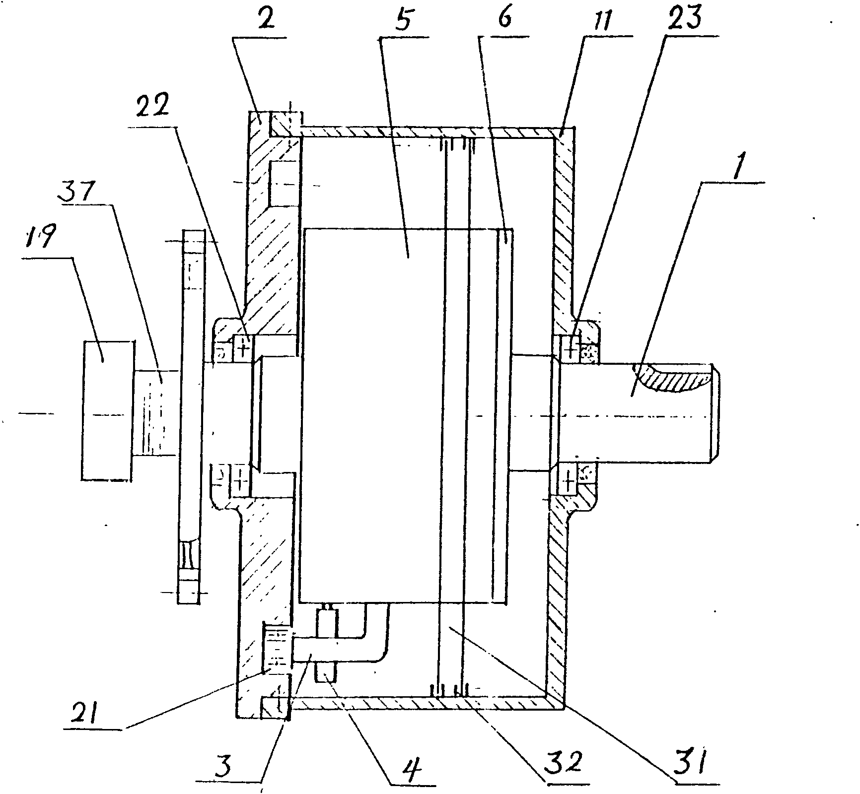
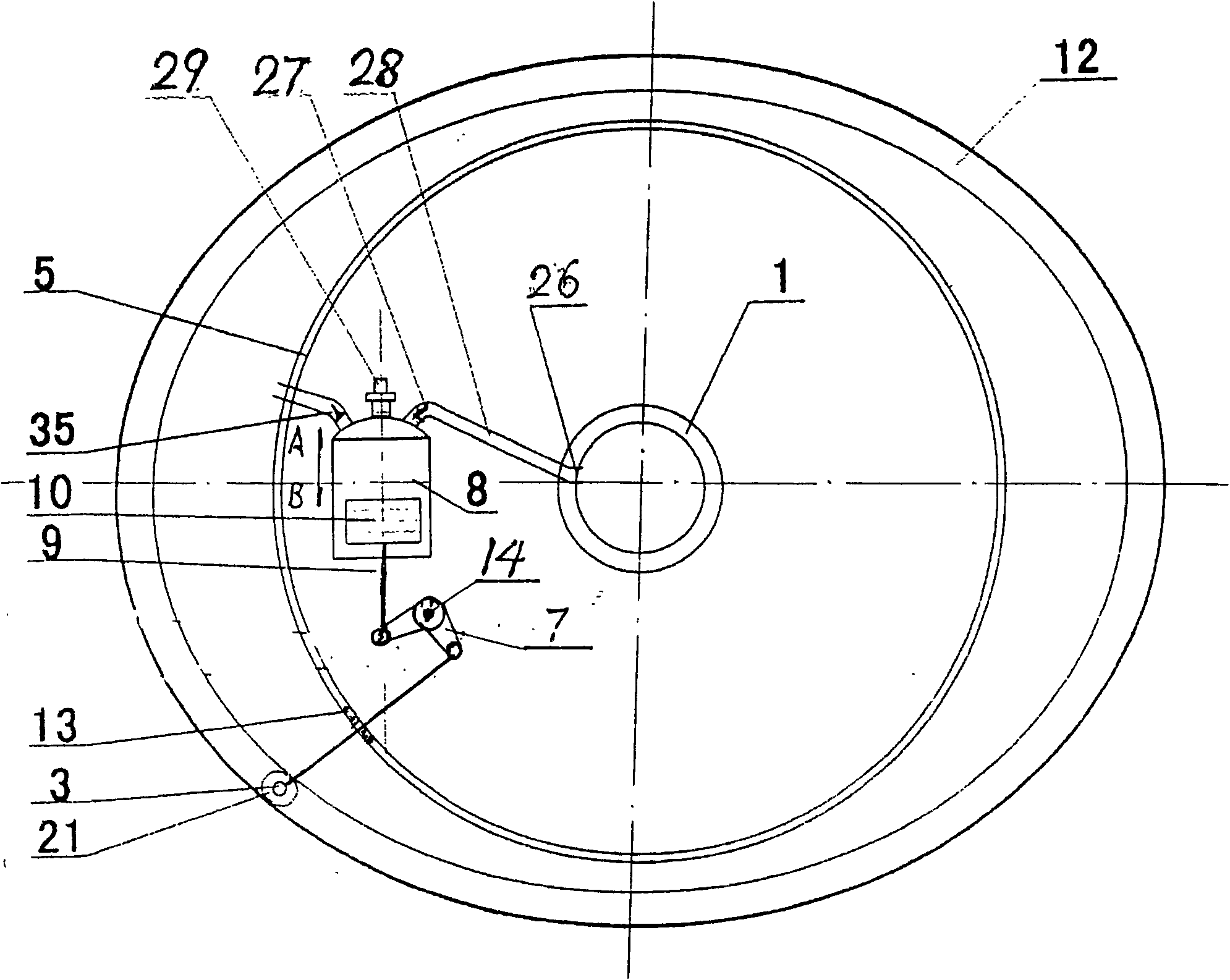
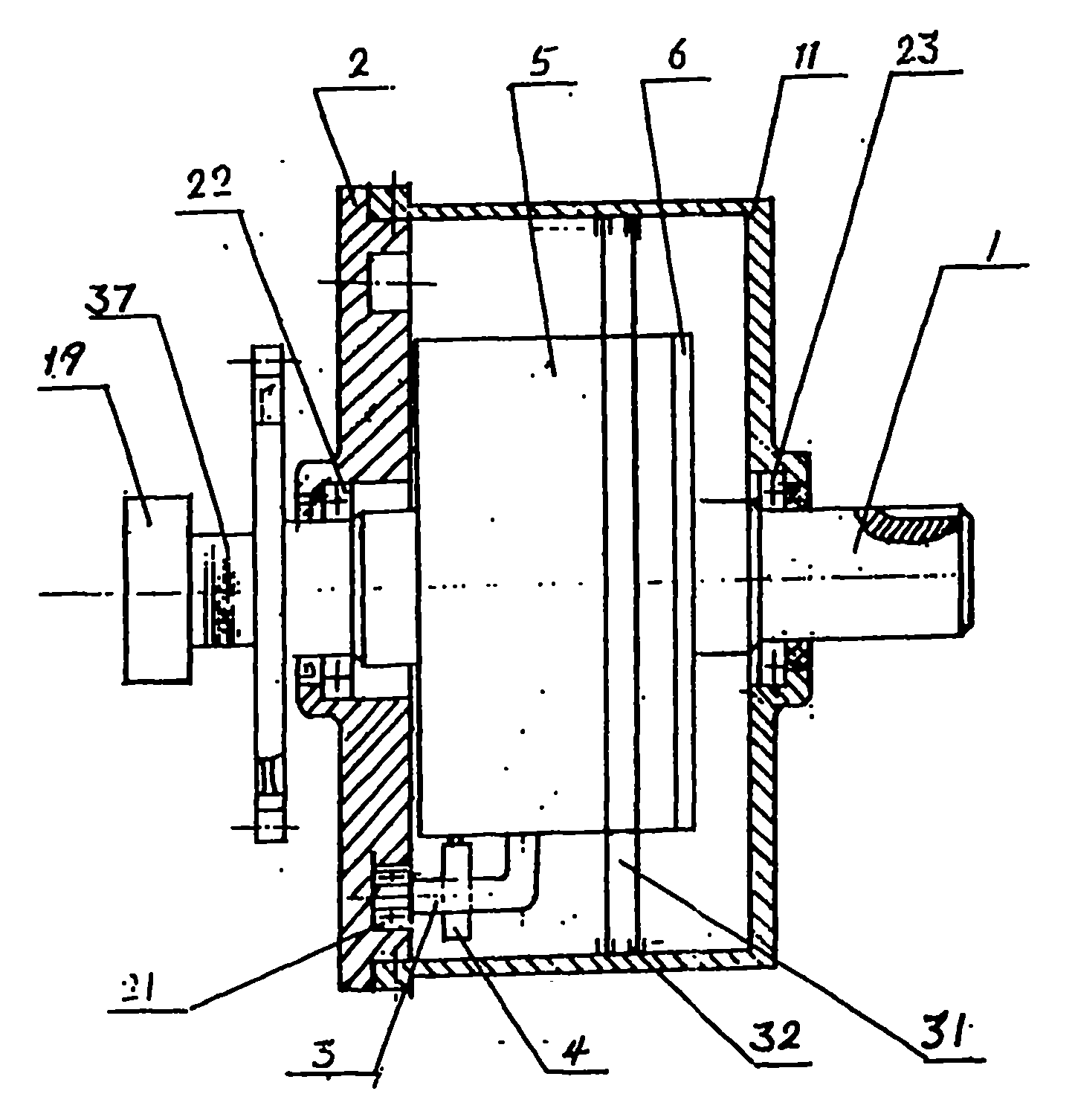
[0029] The present invention will be described in further detail below in conjunction with accompanying drawing description and specific embodiment:

[0030] see figure 1 figure 2A transmission mechanism and its rotary engine of the present invention include a main shaft (1); an elliptical track groove disc body (2); a transmission connecting rod (3); a positioning U-shaped fork (4); a cylindrical rotating cylinder body (5) ;Cylinder end cover (6); Reversing lever (7); Machine head (8); Piston rod (9); Piston (10); Cylindrical casing (1D; Elliptical track groove (12); Seal (13); Reversing lever shaft (14); Head intake oil valve (27); Oil supply manifold (28); Spark plug (29); Exhaust valve (30); Exhaust runner ring (31 ); exhaust runner sealing ring (32); exhaust pipe (33), and corresponding supporting electronic actuators, control units, electronic circuits, etc.

[0031] Design elliptical track groove (major axis - short axis) ÷ 2 = piston stroke S

[0032] Assume that ...


PUM


Abstract

The invention relates to a single-row reciprocating piston type rotor engine, belonging to the field of power generating machines. The engine comprises a main shaft (1), an elliptic orbit groove disc body (2), a transmission connecting rod (3), a positioning U-shaped fork (4), a cylindrical rotary cylinder body (5), a rotary cylinder body end cover (6), a turning lever (7), a turning lever shaft (14), a traditional single cylinder engine nose (8), a piston connecting rod (9), a piston (10), a cylindrical enclosure (11) and the like, wherein the lower end of the transmission connecting rod (3) is provided with a bearing (21) inserted into an elliptic orbit groove (12); a horizontal elbow of the transmission connecting rod (3) passes through the tube wall of the cylindrical rotary cylinder body (5); a perforation is sealed by using a shaft seal (13); the horizontal elbow is connected with one end of the turning lever (7) by using the bearing; the piston connecting rod (9) is connected with the other end of the turning lever (7) also by using the bearing; the turning lever shaft (14) is fixed on the bottom of the rotary cylinder body (5) and is in positioning connection with the turning lever (7) by using the bearing. The invention has the advantages of simple and compact structure, few components, light weight, small volume, high efficiency, energy saving, convenience of maintenance and long service life and not only can be made into a gasoline engine but also can be made into a diesel engine.

Description

1. Technical field [0001] The invention relates to a novel internal combustion engine, which belongs to the field of power machinery. 2. Background technology [0002] The core technical point of the internal combustion engine widely used in the world today is a variable capacity mechanism, which can generate a sufficiently suitable compression ratio, complete the "Otto heat cycle", and output torque to do work. The key core technology is the sealing problem between the piston and the cylinder wall in the unit volume, as well as the energy saving, emission and environmental protection problems. [0003] For more than 100 years, the crank-connecting rod piston internal combustion engine (hereinafter referred to as the crankshaft), which has been dominant in the engine field, has been very mature. In recent years, the engine has entered the "electronic age", and the development of the traditional crankshaft has almost reached "perfect". the point. However, the crank-connecti...

Claims


Application Information

Patent Timeline
Patent Type & Authority Applications(China)
IPC IPC(8): F02B75/32F02B75/02F02B57/02F02F1/10F01M1/02F16H21/10
Inventor 方保林张良栋
Owner SHANGHAI MOSES MARINE ENG
Why Eureka
Try Eureka