
Photoacoustic detecting device and method for glucose concentration in biological fluid

A technology for glucose concentration and photoacoustic detection, applied in measuring devices, material analysis through optical means, instruments, etc.

Active Publication Date: 2019-03-29
NORTHEASTERN UNIV
View PDF19 Cites 0 Cited by
  • Summary
  • Abstract
  • Description
  • Claims
  • Application Information

AI Technical Summary

Problems solved by technology

There have been many reports on trace gas detection devices, and some studies have focused on cancer markers in human breath. However, the miniaturized photoacoustic detection system for biological sample analysis instruments or related methods have not been reported.

Method used


Image

  • Photoacoustic detecting device and method for glucose concentration in biological fluid
  • Photoacoustic detecting device and method for glucose concentration in biological fluid
  • Photoacoustic detecting device and method for glucose concentration in biological fluid

Examples


Embodiment 1

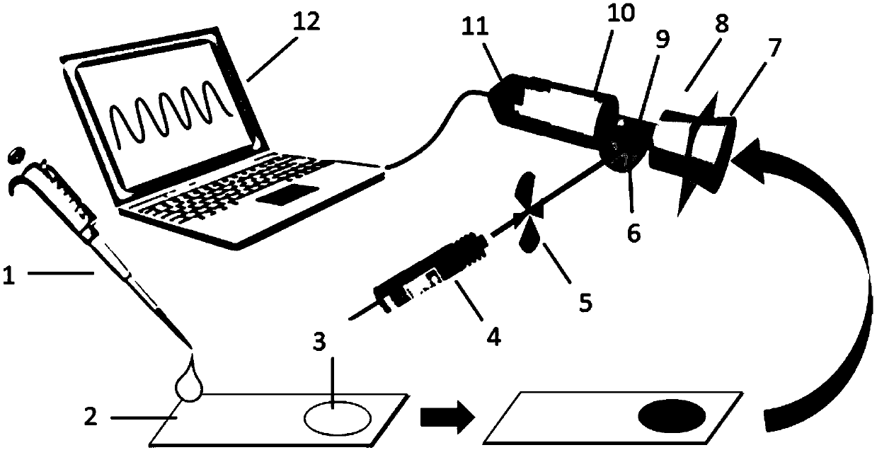
[0059] A photoacoustic detection device for glucose concentration in biological fluids, including a photoacoustic detection system and a sample reaction module. The schematic diagram of the device structure is shown in figure 1 Shown:

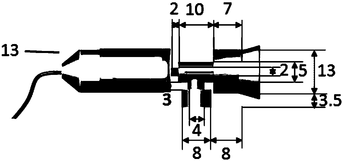
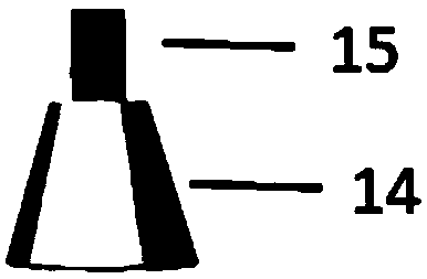
[0060] The photoacoustic device is composed of a laser 4, a chopper 5, a sample holder 7, a photoacoustic cell 8, a microphone 10, a preamplifier 11 and a notebook computer 12, and the laser 4 is modulated into a periodic light source through the chopper 5; The structural representation of the sample holder 7 is as image 3 As shown, the size schematic diagram of the photoacoustic cell 8 is shown as figure 2 As shown, the schematic diagram of the sample holder structure is shown in image 3 As shown, the photoacoustic pool 8 is made of polytetrafluoroethylene, and its length, width, and height are 40mm, 20mm, and 20mm respectively. The pool body is drilled. The hole A on the left side of the photoacoustic pool 8 has an aperture of 13.5mm and...

Embodiment 2

[0066] The structure of the device in this embodiment is the same as in Embodiment 1.

[0067] The method for photoacoustic detection of glucose concentration in human blood by using the above device, comprising the following steps:

[0068] Dilute the freshly obtained blood to the linear range of glucose, add 3 μL of chitosan solution with a mass concentration of 0.6% to the paper chip detection area 3, after drying at room temperature (25°C), add 2 μL of starch potassium iodide solution dropwise, and continue at room temperature Dry (25°C), then add 2 μL of glucose oxidase solution with a concentration of 2 mg / mL dropwise;

[0069] Add 20 μL of diluted human blood dropwise to the paper chip sample area 2, the diluted human blood flows to the paper chip detection area 3 through capillary action, and react at room temperature (25°C) for 30 minutes to form a purple inclusion compound; then the paper chip is detected Area 3 is transferred to the photoacoustic cell 8, the laser ...


PUM

PropertyMeasurementUnit
Diameteraaaaaaaaaa

Abstract

A photoacoustic detecting device and method for glucose concentration in a biological fluid provided by the invention belong to the technical field of photoacoustic detection and analysis. The devicecomprises the photoacoustic detecting device and a sample reaction module, and gives a specific structure and a connection mode, so that the device can be used to sensitively detect the glucose concentration in the biological fluid. A small-scale photoacoustic detection method is provided, and all the light source, the chopper and the microphone used in the device can be powered by a portable power source, which is free from the bulky components in the prior art, has portability, and can be used for on-site detection. During the detection by the method, a paper chip is used as the reaction medium, and a starch potassium iodide system is used as the medium to realize the photoacoustic detection of the glucose concentration in the biological fluid, and realize the analysis of other samples to be detected capable of generating hydrogen peroxide, thereby expanding the scope of photoacoustic detection technology for the analysis of biological samples.

Description

Technical field: [0001] The invention belongs to the technical field of photoacoustic detection and analysis, and in particular relates to a photoacoustic detection device and method for glucose concentration in biological fluid. Background technique: [0002] Photoacoustic (Photoacoustic) technology is to irradiate the sample containing the analyte with an excitation light source, so that the analyte transitions from the ground state to the excited state, and produces a thermal effect through the non-radiative transition to the ground state, and then generates sound waves, which are quantified by detecting the sound intensity Analysis technique. Traditional absorption and emission optical detection instruments are more suitable for homogeneous samples, and have high requirements for sample morphology, matrix, and optical properties, and cannot realize optical signal detection of complex matrix samples. Photoacoustic spectroscopy can be used for the detection of analytes in...

Claims


Application Information

Patent Timeline
IPC IPC(8): G01N21/17
CPCG01N21/1702
Inventor 于永亮张雅洁王建华
Owner NORTHEASTERN UNIV
Learn More