Clutch

A clutch and column technology, applied in the field of clutches, can solve the problems of huge oil supply system, friction and wear, heating, inconvenient control, etc., and achieve the effects of reducing mechanical energy loss, strong power output, and remarkable fuel saving effect

Inactive Publication Date: 2012-07-04
李占军
View PDF5 Cites 3 Cited by
  • Summary
  • Abstract
  • Description
  • Claims
  • Application Information

AI Technical Summary

Problems solved by technology

[0002] Traditional mechanical clutches have defects such as impact, large inertia, severe friction and wear and heat generation, short service life, and inconvenient control; traditional fluid-viscous clutches control the transmitted torque by adjusting the thickness of the oil film, which can effectively overcome Disadvantages of traditional mechanical clutches, but it requires a huge oil supply system and complex control devices, the whole system is bulky and expensive

Method used


Image

  • Clutch
  • Clutch
  • Clutch

Examples


Embodiment 1

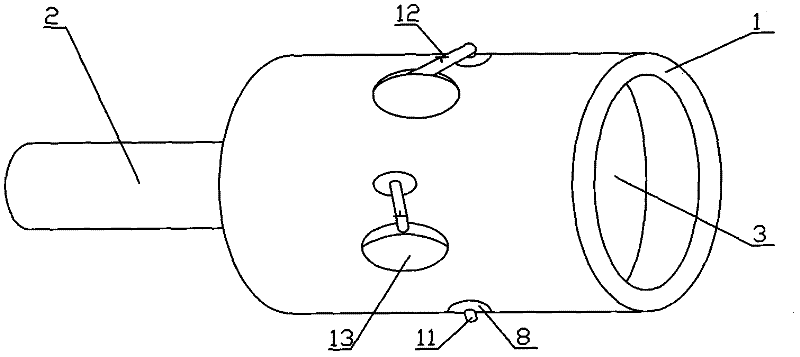
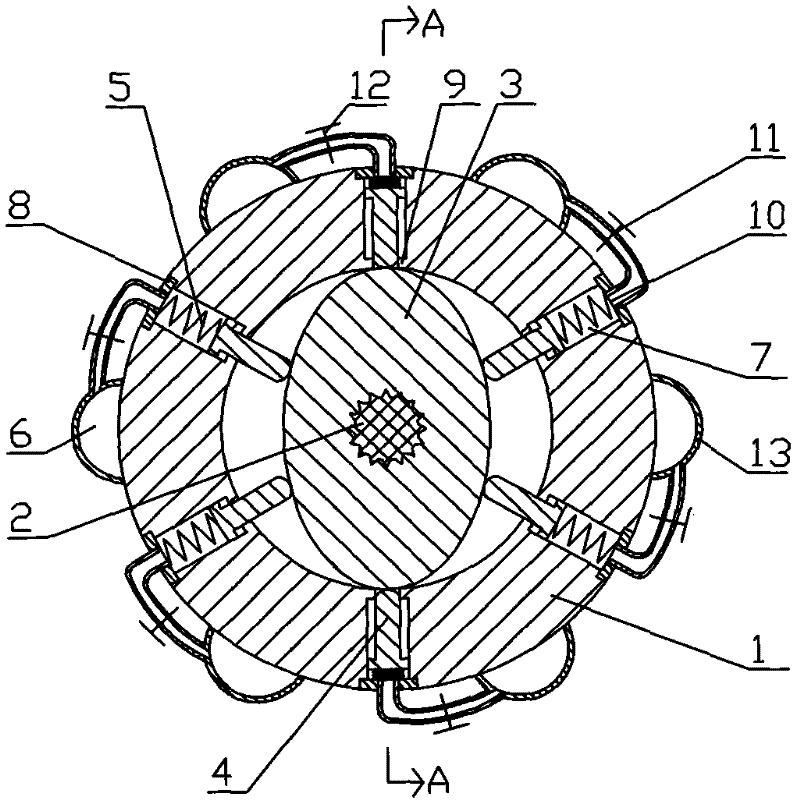
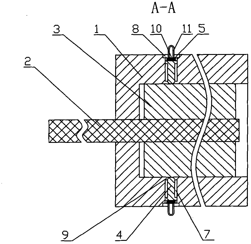
[0025] Embodiment 1: as figure 1 , figure 2 , image 3 As shown, a clutch includes a cylindrical driving shaft 1, a driven shaft 2, a driven disc 3, a compression clamp 4, a return spring 5 and a liquid storage device 6, wherein one end of the driven shaft 2 passes through the cylindrical At the center of the bottom end of the driving shaft 1, a driven disk 3 is fixed on the top of the driven shaft 2 in the cylindrical driving shaft 1. The driven disk is a 3-elliptical column structure, and the top of the driven shaft 2 is connected to the elliptical surface of the driven disk 3. Vertically fixed, on the outer wall of the cylindrical driving shaft 1, there are 6 clamping column holes 7 evenly arranged along a cross section perpendicular to the axial direction of the cylindrical driving shaft 1, and the pressing clamping holes 7 on the outer wall of the cylindrical driving shaft 1 The opening of the column hole 7 is sealed and screwed with a compression column hole sealing c...

Embodiment 2

[0026] Embodiment 2: as Figure 4 , Figure 5 Shown, a kind of clutch, compared with embodiment 1, only liquid storage device 6 is different, other structures are all the same as embodiment 1, and wherein liquid storage device 6 comprises hollow liquid storage device housing 14, in liquid storage device housing A piston 15 sliding up and down is provided in the cavity of the body 14, and the cavity of the liquid storage device housing 14 is divided into an air chamber 16 and a liquid storage chamber 17; Oil hole 18, the oil outlet hole 18 communicates with the liquid storage chamber 17, and the oil pipe 11 is connected on the oil outlet hole 18; an air hole 9 is arranged on the top of the liquid storage device housing 14, and the air hole 9 communicates with the air chamber 16; The liquid cavity 17 is filled with hydraulic oil.

Embodiment 3

[0027] Embodiment 3: as Figure 6 As shown, a clutch, compared with embodiment 2, only the driven disc 2 is different, and other structures are the same as embodiment 1, the cross section of the driven disc 2 is a special-shaped equilateral triangle, along a cylindrical driving shaft 1 There are 3 clamping post holes 7 evenly arranged in the cross-section perpendicular to the axial direction; or as Figure 7 As shown, the cross-section of the driven disc 2 is a special-shaped square, and there are four clamping post holes 7 evenly arranged along a cross-section perpendicular to the axial direction of the cylindrical driving shaft 1; or as Figure 8 As shown, when the cross-section of the driven disc 2 is a special-shaped regular pentagon, there are five compression clamp holes 7 evenly arranged along a cross-section perpendicular to the axial direction of the cylindrical driving shaft 1; or as Figure 9 As shown, the cross section of the driven disc 2 is a special-shaped regu...


PUM


Abstract

The invention discloses a clutch. The clutch comprises a cylindrical driving shaft, a driven shaft, a compactness clamping column, a restoring spring, a liquid storage device and a driven disc, wherein one end of the driven shaft penetrates through the center of the bottom of the cylindrical driving shaft; the driven disc is fixed on the top of the driven shaft; a compactness clamping column hole is formed in the cylindrical wall of the cylindrical driving shaft; a compactness clamping column hole sealing cover is arranged at the opening of the compactness clamping column hole; the compactness clamping column is arranged in the compactness clamping column hole; the restoring spring is arranged in the compactness clamping column hole; an oil hole is formed in the column hole sealing cover; the liquid storage device is arranged on the outer wall of the cylindrical driving shaft; and the oil hole is communicated with the liquid storage device through an oil pipe. The invention has the advantages that: the power for the clutch can be timely, safely, reliably and effectively on or off, can be in a semi-linkage state and a separation state for long time, and has strong power output; and when the clutch is in semi-linkage, the main body is not connected with a separation bolt, so loss of a large quantity of mechanical energy is reduced, and the energy-saving effect is remarkable. The clutch is compact in structure, difficult to damage, simple in control and long in service life.

Description

Technical field: [0001] The invention relates to a clutch device, in particular to a clutch. Background technique: [0002] Traditional mechanical clutches have defects such as impact, large inertia, severe friction and wear and heat generation, short service life, and inconvenient control; traditional fluid-viscous clutches control the transmitted torque by adjusting the thickness of the oil film, which can effectively overcome The shortcomings of the traditional mechanical clutch, but it requires a huge oil supply system and a complex control device, the whole system is bulky and expensive. Invention content: [0003] The object of the present invention is to provide a clutch with simple structure, not easy to damage, long service life and simple control. [0004] The present invention is implemented by the following technical solutions: a clutch, which includes a cylindrical driving shaft, a driven shaft, a pressing clamp, a return spring, a liquid storage device and a...

Claims


Application Information

Patent Timeline
Patent Type & Authority Applications(China)
IPC IPC(8): F16D25/065
Inventor 李占军
Owner 李占军
Why Eureka
Try Eureka