Simple fixed-shaft type transmission assembly for loader

A gearbox and fixed-shaft technology, which is applied to mechanical equipment, engine components, engine seals, etc., can solve the problem of reducing the working efficiency and service life of the gearbox, wear of the primary worm gear and secondary worm gear, and force converter movement Vibration and other problems to achieve the effect of prolonging the interval between out-of-box maintenance, solving vibration and shock, and increasing output power

Inactive Publication Date: 2012-07-04
罗庆繁
View PDF7 Cites 1 Cited by
  • Summary
  • Abstract
  • Description
  • Claims
  • Application Information

AI Technical Summary

Problems solved by technology

[0003] Since the first shaft is the gear shaft that inputs the first-stage gear and the second-stage gear set, the shaft that enters the second-stage gear is equipped with a power converter movement, and the front end of the shaft that enters the second-stage gear is suspended and not installed on the gearbox housing. The bearing support of the variator will cause the vibration of the variator movement, which will cause the wear of the primary and secondary worm gears in the variator movement
Since the second shaft is a two-stage concentric shaft with the front section and the rear section separated, the front section and the rear section are only connected by a sun gear with an involute internal spline to two sections of involute external splines near the end to form a concentric shaft. The coaxiality of the two sections and the rigidity of the connection are greatly affected by the machining accuracy of the involute inner and outer splines. When the gearbox is in reverse gear or first gear, it is easy to cause vibration, causing the first gear planetary carrier, Reverse planet carrier, planetary shaft, bearing, planetary gear and other parts are damaged, which reduces the working efficiency and service life of the gearbox, and affects the use of the whole machine, and this situation has not been well resolved for a long time

Method used


Image

  • Simple fixed-shaft type transmission assembly for loader
  • Simple fixed-shaft type transmission assembly for loader
  • Simple fixed-shaft type transmission assembly for loader

Examples


Embodiment Construction

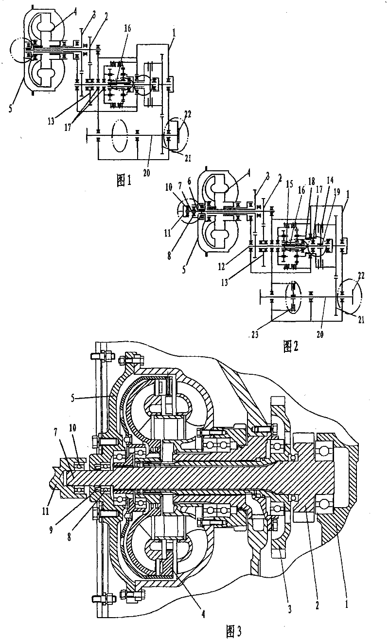
[0014] pass figure 1 with figure 2 It can be seen from the comparison that the simple fixed axis loader gearbox assembly of the present invention mainly has five improvements to the original loader gearbox assembly (outlined by the ellipse with double dotted line in the figure): 1. The through hole in the middle of the cover wheel and the forward cylindrical section of the input first-stage gear; 2. The middle part of the second shaft; 3. The right part of the 2nd shaft; 4. The middle left part of the 3rd shaft; 5. The third shaft at the right end.

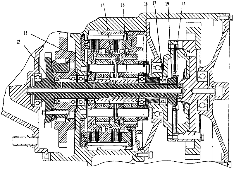
[0015] Refer to attached figure 2 with 3 , In the gearbox housing 1 of the present invention, one shaft, two shafts and three shafts are also installed. The first shaft is also the gear shaft of the input primary gear 2 and the input secondary gear 3, the input primary gear 2 is a solid shaft, the input secondary gear 3 is a hollow shaft, and the input secondary gear shaft is set outside the input primary gear shaft , the p...


PUM


Abstract

A simple fixed-shaft type transmission assembly for a loader belongs to loader components. A first shaft is a gear shaft sleeved with a primary input gear of a solid shaft and a secondary input gear of a hollow shaft, a covering gear is mounted on the solid shaft, and a variable-force device core is mounted on the hollow shaft. A bearing-type overrunning clutch and a sun gear are mounted on a second shaft, a third shaft is an output shaft with a gear in the middle, and a front flange and a rear flange are mounted at two ends of the output shaft. A through hole is arranged in the middle of the covering gear, a cylindrical section extending forwards out of the through hole is arranged at the front end of the primary input gear, an auxiliary bearing and a sealing ring are mounted between the cylindrical section and the through hole, and a support bearing supported in a spindle end seat hole of an engine is further mounted at the front end of the cylindrical section. The second shaft is a stepped integral shaft, the overrunning clutch is mounted at the outer end of the second shaft, a direct-gear driving friction plate is mounted at the inner end of the second shaft, and an external spline matched with an internal spline of the sun gear is arranged in the middle of the second shaft. By the aid of the simple-fixed shaft type transmission assembly for the loader, vibration of the variable-force device core can be greatly relieved, wear of a primary worm gear and a secondary worm gear is avoided, damage of first-gear and reverse-gear parts is avoided, the efficiency of a transmission is improved, and the service life of the transmission is prolonged.

Description

technical field [0001] The invention relates to a loader component, in particular to a planetary hydraulic power shift gearbox of a heavy loader. Background technique [0002] The gearbox is the most important, complex and expensive part of the loader. At present, most of the gearboxes of existing heavy loaders such as ZL40, ZL50 or ZL80 use planetary hydraulic power shift gearboxes. This kind of gearbox not only transmits large torque, but also is easy to operate, but the structure is complex, and the processing and installation accuracy high. In its gearbox housing, one shaft, two shafts and three shafts are installed. The first shaft is the gear shaft of the input primary gear and the input secondary gear set, the input primary gear is a solid shaft, the input secondary gear is a hollow shaft, the input secondary gear is set outside the input primary gear shaft, and the input secondary gear The shaft of the shaft is equipped with a force variator movement. The inner e...

Claims


Application Information

Patent Timeline
Patent Type & Authority Applications(China)
IPC IPC(8): F16H57/08F16J15/54F16J15/16
Inventor 罗庆繁罗宇杰黄艳英
Owner 罗庆繁
Why Eureka
Try Eureka