Rotary multi-way valve

A multi-way valve and rotor technology, applied in multi-way valves, valve details, diaphragm valves, etc., can solve problems such as cross-contamination, liquid leakage, and easy wear of end face seals, achieving strong designability and flexible and convenient replacement

Active Publication Date: 2012-07-04
INST OF PROCESS ENG CHINESE ACAD OF SCI
View PDF7 Cites 15 Cited by
  • Summary
  • Abstract
  • Description
  • Claims
  • Application Information

AI Technical Summary

Problems solved by technology

The rotary multi-way valves currently used basically adopt end face seals. For example, the rotary multi-way valves reported in patents such as CN200720100464.5, CN200620167076.4 and CN200620135470. , the end face seal is easy to wear, causing liquid leakage and cross-contamination

Method used


Image

  • Rotary multi-way valve
  • Rotary multi-way valve
  • Rotary multi-way valve

Examples


Embodiment 1

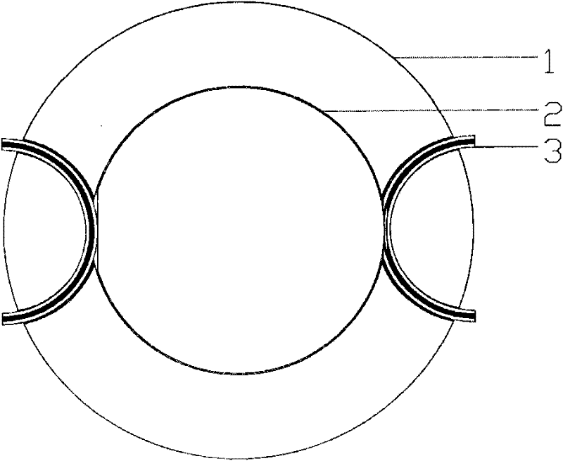
[0101] use as Figure 1a The pressure switch shown is released, the inner rotor and outer stator mode; its overall structure adopts the following Figure 2a Shown; the distribution of fluid channels on the middle plate is as follows Figure 9a As shown, the four-way distribution method is adopted; three intermediate plates are stacked, there is a chassis under it, and a top plate above, and the fastening method of the bottom plate, the middle plate and the top plate is bolted; the outer diameter of the middle plate is 160mm, the inner diameter is 108mm, and its upper surface carries the closing mechanism—the groove of the silicone tube is a semi-circular ring, the radius of the ring body is 60mm, and the corresponding circular tube diameter is 12mm; the rotor adopts such as Figure 7a , 7b , 7c and 7d show the form of the inner rotor, the diameter of the main cylinder is 100mm, the height of the gap is 10mm, the distribution of the gap is as follows Figure 7a , 7b As shown...

Embodiment 2

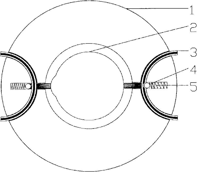
[0104] use as Figure 1d The pressure-on-release type shown is an inner stator and outer rotor mode; its overall structure adopts the following Figure 2b Shown; the distribution of fluid channels on the middle plate is as follows Figure 9b-1 As shown, the five-way distribution method is adopted; only one middle plate is used, there is a bottom plate under it, and a top plate on the top, and the fastening method of the bottom plate, the middle plate and the top plate is bolted; the outer diameter of the middle plate is 100mm , the inner diameter is 50mm, and its upper surface has a groove for carrying the closing mechanism 3 and the pressing mechanism 4; the rotor adopts such as Figure 9b-2 In the form of the outer rotor shown, the outer diameter of the main cylinder is 160mm, the inner diameter is 118mm, the height of the protrusion is 10mm, and there is only one protrusion; the closing mechanism adopts a silicone tube as shown in Figure 3a, the outer diameter is 10mm, and...

Embodiment 3

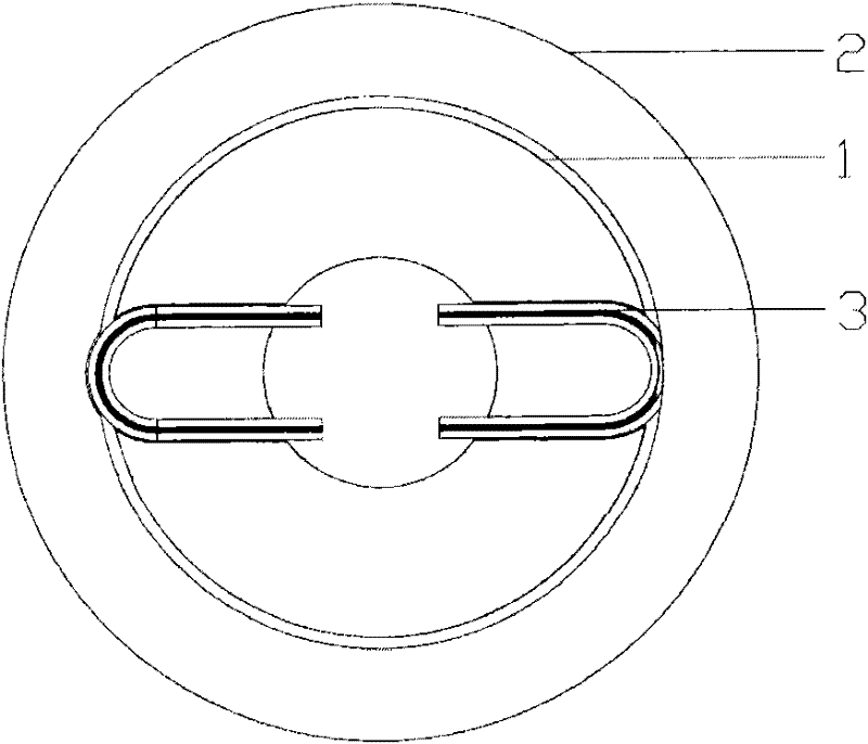
[0107] use as Figure 1d The pressure-opening and loose-closing type shown; its overall structure adopts the following Figure 2c As shown, it is the upper stator and lower rotor mode; the distribution of the fluid channels on the upper stator is as follows Figure 9c-1 As shown, a six-way distribution method is adopted; the outer diameters of the upper stator and the lower rotor are both 180mm, the inner diameter of the upper stator is 50mm, the inner diameter of the lower rotor is 70mm, the diameter of the middle shaft is 50mm, and the upper stator is fixed on the middle shaft. The lower rotor is connected to the central shaft through an ordinary bearing, the inner diameter of which is 50mm, and the outer diameter is 70mm; Institutions such as Figure 4d-1 and 4d-2 The pressure-opening-release-closing mechanism shown; the relative positional relationship of the lower rotor, the pressing mechanism and the closing mechanism are as follows: Figure 5c-2 As shown, only its i...


PUM


Abstract

The invention relates to a rotary multi-way valve, which comprises a plurality of closing mechanisms (3), a stator (1) and a rotor (2). The stator (1) and the rotor (2) are arranged coaxially, a part of each of the closing mechanisms (3) is penetratingly arranged in the stator (1) and on the plane perpendicular to a rotary shaft, and the closing mechanisms (3) are controlled to be on or off by matching with notches or projections on the rotor (2). Fluid passages of the rotary multi-way valve are independent mutually completely so that cross pollution of different fluids can be avoided. Each of the closing mechanisms forming the fluid passages is an independent component and can be changed more flexibly and conveniently so that scrap of the integral valve due to one abraded fluid passage is avoided. The rotary multi-way valve has higher designability, and the number of the fluid passages can be changed by changing different middle discs or using different numbers of middle discs according to specific needs.

Description

technical field [0001] The invention relates to a valve structure commonly used in petroleum exploitation, chemical industry and other industries, in particular, the invention relates to a rotary multi-way valve. Background technique [0002] Rotary multi-way valves are widely used in petroleum exploration, chemical industry and other industries. The rotary multi-way valves currently used basically adopt end face seals. For example, the rotary multi-way valves reported in patents such as CN200720100464.5, CN200620167076.4 and CN200620135470. , The end face seal is easy to wear, causing liquid leakage and cross-contamination. Contents of the invention [0003] The object of the present invention is to provide a rotary multi-way valve in order to solve the above problems. [0004] In order to achieve the above object of the present invention, the present invention provides a rotary multi-way valve, comprising: a closing mechanism 3 and a coaxial stator 1 and rotor 2; [0...

Claims


Application Information

Patent Timeline
Patent Type & Authority Applications(China)
IPC IPC(8): F16K11/02F16K7/06F16K31/44
Inventor 杨鹏波丛威
Owner INST OF PROCESS ENG CHINESE ACAD OF SCI
Why Eureka
Try Eureka