Heat tube type all-glass vacuum solar collector tube

An all-glass, heat-collecting tube technology, applied in solar collectors, solar thermal devices, solar thermal energy, etc., can solve problems such as low compressive strength, reduced thermal efficiency, and high pressure

Active Publication Date: 2012-07-04
TIANPU NEW ENERGY TECH
View PDF11 Cites 4 Cited by
  • Summary
  • Abstract
  • Description
  • Claims
  • Application Information

AI Technical Summary

Problems solved by technology

[0002] In solar collectors and water heaters, there are three ways to combine glass vacuum solar collector tubes and heat pipes. The first is to place metal heat pipes with heat absorbers in single-layer glass tubes, and vacuumize the gap between the two, and use The disadvantage of sealing the vacuum cavity by metal and glass thermal compression sealing is that the properties of metal and glass are very different. Therefore, the process of sealing the vacuum cavity by thermal compression sealing is complicated, difficult, unreliable, and high in cost; The second is to insert a metal heat pipe with a heat absorbing body (such as fins) into an all-glass vacuum solar heat collector. Since the gap between the two is not vacuum, the application effect is not ideal and the cost is high; the third is The inner glass tube of the all-glass vacuum solar collector tube is used as the shell of the evaporation section of the heat pipe, and the glass condensation section of the heat pipe is also provided. The biggest advantage is that the structure is simple, the cost is low, the application effect is good, and it is conducive to popularization and

Method used


Image

  • Heat tube type all-glass vacuum solar collector tube
  • Heat tube type all-glass vacuum solar collector tube
  • Heat tube type all-glass vacuum solar collector tube

Examples


Embodiment 1

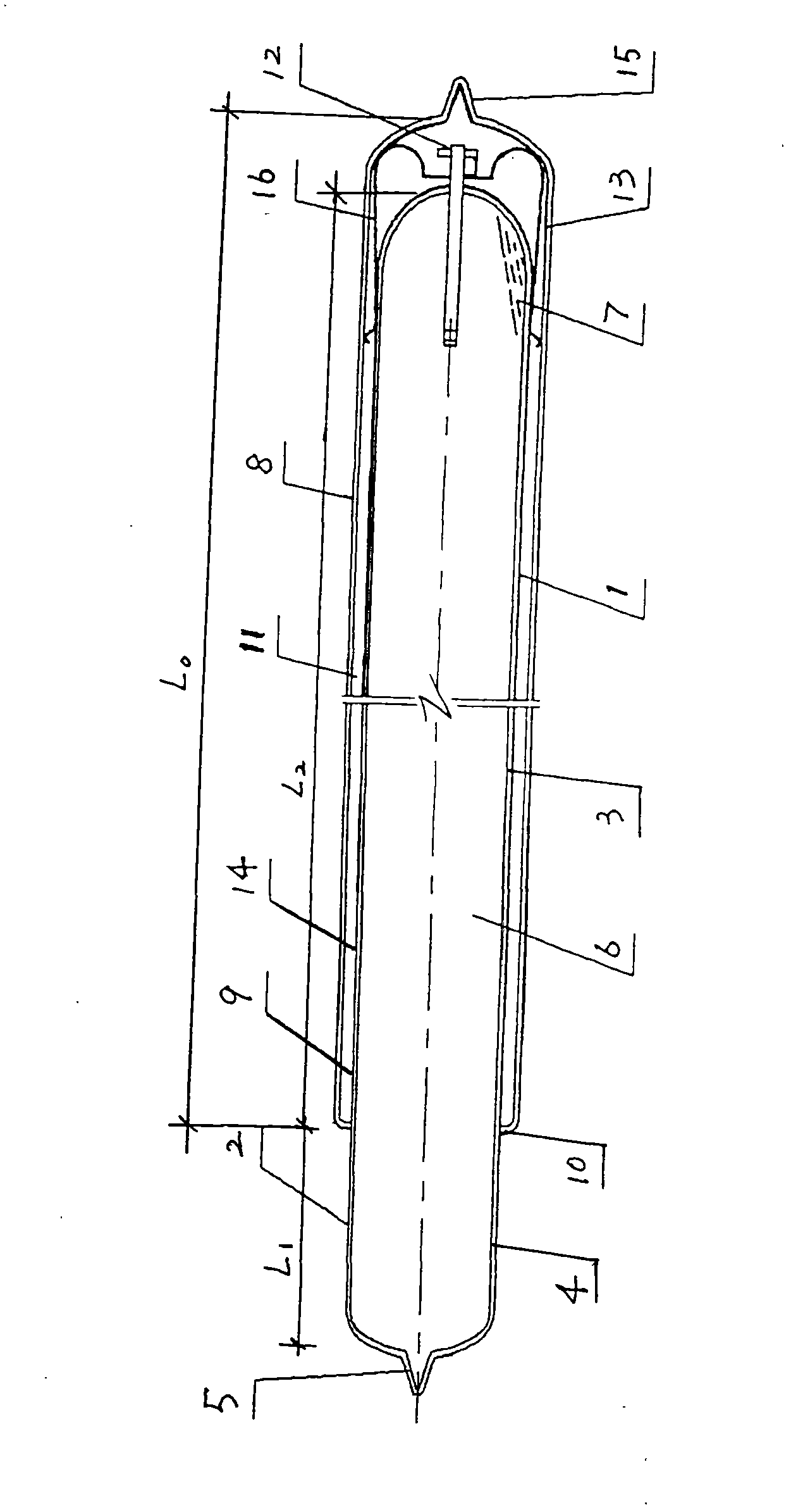
[0019] according to figure 1 As shown in the structure, the heat pipe type all-glass vacuum solar heat collector has a length L. 1800mm, the outer diameter of the cover glass tube 8 is 58mm, the wall thickness is 1.8mm, the outer diameter of the inner glass tube 9 is 47mm, and the wall thickness is 2.6mm, the outer extension length L of the inner glass tube 9 1 ——that is, the length of the condensation section 4 is 100 mm, the glass wall thickness of the heat-sealed end 5 is 1.8 mm, and the length of the evaporation section 3 is L 2 is 1770mm; the total volume of the vacuum chamber 6 is V 1 2566cm 3 , the heat transfer medium 7 is distilled water, and its liquid phase volume is V 2 5.1ml, the volume ratio between the two is V 2 / V 1 = 0.2%.

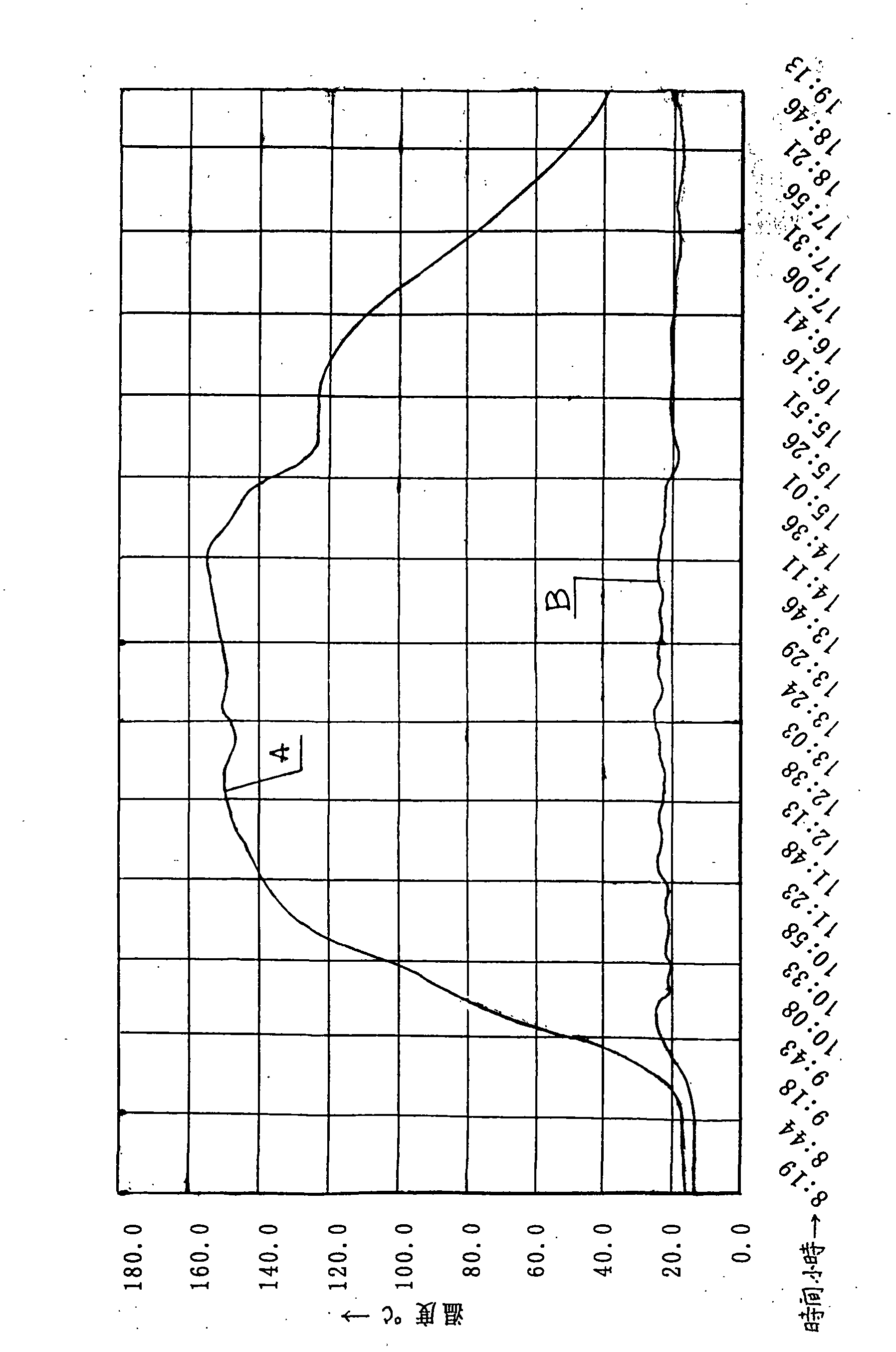
[0020] As shown in Table 1, it is the condensing section 4 of the single heat pipe type all-glass vacuum solar collector tube of embodiment 1 inserted in the test water tank of 10 liters of water, and the thermal performance test re...


PUM


Abstract

The invention discloses a heat tube type all-glass vacuum solar collector tube which belongs to the field of solar energy utilization equipment and is formed by combining an all-glass vacuum solar collector tube (1) and an all-glass heat tube (2); the evaporation section (3) of the all-glass heat tube (2) is formed by an inner glass tube (9) in the all-glass evacuated solar collector tube (1), and the condensation section (4) of the all-glass heat tube (2) is formed by coaxially extending the inner glass tube (9) outwards from a ring seal cup opening (1) of the all-glass vacuum solar collector tube (1) with equal diameter; the wall thickness of the inner glass tube (9) is more than that of a cover glass tube (8) of the all-glass vacuum solar collector tube (1) by 0.8-1.2 mm, and the thickness of the glass wall of the hot seal end (5) on the condensation section (4) is equal to the thickness of the wall of the cover glass tube (8); a heat transfer medium (7) is filled in a vacuum cavity (6) of the all-glass heat tube (2), and the volume ratio of the heat transfer medium (7) and the vacuum cavity (6) is 0.05%-0.4%; and the length L1 of the condensation section (4) is 70-150mm. The heat tube type all-glass evacuated solar collector tube integrates the heat collection and heat transferring, is quick in heat transfer speed, high in heat efficiency, good in performance, safe and reliable, easy to manufacture, low in cost, convenient to install and transport and easy to promote and apply, and the national performance standards can be met.

Description

technical field [0001] The invention belongs to the field of solar energy utilization equipment, and relates to a heat pipe type all-glass vacuum solar heat collection pipe. Background technique [0002] In solar collectors and water heaters, there are three ways to combine glass vacuum solar collector tubes and heat pipes. The first is to place metal heat pipes with heat absorbers in single-layer glass tubes, and vacuumize the gap between the two, and use The disadvantage of sealing the vacuum cavity by metal and glass thermal compression sealing is that the properties of metal and glass are very different. Therefore, the process of sealing the vacuum cavity by thermal compression sealing is complicated, difficult, unreliable, and high in cost; The second is to insert a metal heat pipe with a heat absorbing body (such as fins) into an all-glass vacuum solar heat collector. Since the gap between the two is not vacuum, the application effect is not ideal and the cost is high;...

Claims


Application Information

Patent Timeline
IPC IPC(8): F24J2/46F24J2/32F24S10/95
CPCY02E10/44
Inventor 罗赞继李峰程翠英
Owner TIANPU NEW ENERGY TECH
Why Eureka
Try Eureka