In-situ preparation method of carbonized film on surface of Fe-Ni-Cr bipolar plate

1. fe-ni-cr, surface carbonization technology, applied in the direction of battery electrodes, electrical components, circuits, etc. To avoid problems such as falling off, to achieve the effects of not being easily deformed, improving electrical conductivity and corrosion resistance, and having good corrosion resistance

Inactive Publication Date: 2013-10-02
WUHAN UNIV OF TECH
View PDF2 Cites 2 Cited by
  • Summary
  • Abstract
  • Description
  • Claims
  • Application Information

AI Technical Summary

Problems solved by technology

Dalian Institute of Chemical Physics has also explored the deposition of carbon film on the surface of the iron base. Although the corrosion resistance has been improved to a certain extent, the carbon film is easy to fall off during the long-term operation of the battery.
(3) Preparation of multilayer film: Li Moucheng of Shanghai University and others invented a patent for preparing a three-layer film on the iron-based surface for surface modification. The inner and outer layers are SnO 2 , IrO 2 , the middle layer is Cr or Mo, and the coating thickness is 0.1-50μm, which has obtained a satisfactory corrosion resistance effect, but it is also expensive
[0006] So far, the coating technology on various substrates is immature, especially in terms of cost reduction, and coatings on iron-based surfaces cannot fully meet the requirements for fuel cell operation
This is mainly due to the fact that the prepared coatings are all deposited by means of PVD or CVD, and there are certain surface defects.

Method used


Image

  • In-situ preparation method of carbonized film on surface of Fe-Ni-Cr bipolar plate
  • In-situ preparation method of carbonized film on surface of Fe-Ni-Cr bipolar plate
  • In-situ preparation method of carbonized film on surface of Fe-Ni-Cr bipolar plate

Examples


Embodiment 1

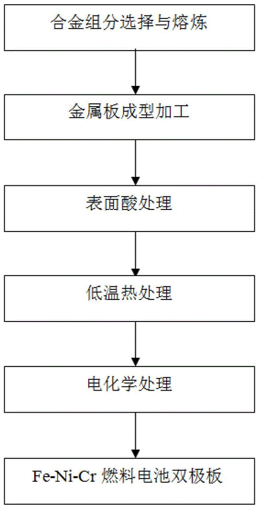
[0031] Such as figure 1 Shown, the in-situ preparation method of the carbide film on the surface of Fe-Ni-Cr bipolar plate, it comprises the following steps:

[0032] (1) Selection and smelting of alloy components: According to the composition of 38% Fe (atomic percentage), 33% Ni (atomic percentage), and 29% Cr (atomic percentage), Fe is obtained by vacuum induction melting 38 Ni 33 Cr 29 Alloy (vacuum induction melting is a conventional method);

[0033] (2) Metal plate forming processing: process the above alloy into a metal plate with a flow field according to conventional methods;

[0034] (3) Surface chemical treatment: Place the metal plate with flow field in HF aqueous solution with a volume concentration of 47%, soak it at 25°C for 8 minutes, take it out, wash it with water, and dry it. Then put it into a vacuum furnace, pass argon, heat treatment at 250 ° C for 2 hours, and then cool with the furnace; then put in H 2 SO 4 and HF mixed aqueous solution, H 2 SO ...

Embodiment 2

[0044] Such as figure 1 Shown, the in-situ preparation method of the carbide film on the surface of Fe-Ni-Cr bipolar plate, it comprises the following steps:

[0045] (1) Selection and smelting of alloy components: According to the composition of 37% Fe (atomic percentage), 34% Ni (atomic percentage), and 29% Cr (atomic percentage), Fe is obtained by vacuum induction melting 37 Ni 34 Cr 29 Alloy (vacuum induction melting is a conventional method);

[0046] (2) Metal plate forming processing: process the above alloy into a metal plate with a flow field according to conventional methods;

[0047] (3) In-situ treatment of the surface: place the metal plate with a flow field in an HF aqueous solution with a volume concentration of 45%, treat it at 30°C for 9 minutes, take it out, wash it with water, and dry it; then put it into a vacuum furnace, pass argon, Heat treatment at 300°C for 1 hour; then put in H 2 SO 4 and HF mixed aqueous solution, H 2 SO 4 The concentration of...

Embodiment 3

[0050] Such as figure 1 Shown, the in-situ preparation method of the carbide film on the surface of Fe-Ni-Cr bipolar plate, it comprises the following steps:

[0051] (1) Selection and smelting of alloy components: according to the composition of 39% Fe (atomic percentage), 33% Ni (atomic percentage), and 28% Cr (atomic percentage), Fe is obtained by vacuum induction melting 39 Ni 33 Cr 28 Alloy (vacuum induction melting is a conventional method);

[0052] (2) Metal plate forming processing: process the above alloy into a metal plate with a flow field according to conventional methods;

[0053] (3) Surface in-situ treatment: place the metal plate in a 50% HF aqueous solution, treat it at 20°C for 7 minutes, take it out, wash it with water, and dry it. Then put it into a vacuum furnace, pass through argon, and heat-treat at 230°C for 3 hours. then put in H 2 SO 4 and HF mixed aqueous solution, H 2 SO 4 The concentration of the substance is 0.48mol / L, the concentration ...


PUM

PropertyMeasurementUnit
corrosion current densityaaaaaaaaaa

Abstract

The invention belongs to the technical field of fuel cells and provides an in-situ preparation method of a carbonized film on the surface of a Fe-Ni-Cr bipolar plate. The in-situ preparation method is characterized by comprising the following steps of: (1) alloy component selecting and melting, namely, mixing the components based on that the atomic percentage content of the component Fe is x, the atomic percentage content of the component Ni is y and the atomic percentage content of the component Cr is z and carrying out vacuum induction melting on the FexNiyCrz alloy, wherein x is equal to 37-39%, y is equal to 32-34%, z is equal to 28-30% and the sum of x, y and z is 100%; (2) metal plate forming processing, namely, processing the FexNiyCrz alloy into a metal plate with a flow field according to the conventional method; and (3) in-situ surface treatment, namely, carrying out surface acid treatment (a), low-temperature heating treatment (b) and electrochemical treatment (c) on the metal plate with the flow field obtained in the step (2) in sequence, thus obtaining the Fe-Ni-Cr alloy bipolar plate of a fuel cell. The bipolar plate of the fuel cell, prepared by using the method, has excellent corrosion resistance and electrical conductivity, and is simple in manufacturing process, low in cost, not easy to deform and suitable for assembling fuel cell stacks.

Description

technical field [0001] The invention belongs to the technical field of fuel cells, and in particular relates to an in-situ preparation method of a carbonized film on the surface of a Fe-Ni-Cr bipolar plate. Background technique [0002] Proton membrane fuel cells have the characteristics of cleanness, high efficiency, mobility, and mild operating conditions, and have important application values ​​in the fields of transportation, aerospace, and electronic communications. A bipolar plate is a plate material that connects single cells in series. It needs to meet various performance requirements, including good electrical conductivity, excellent corrosion resistance (including acid corrosion, oxidative moisture corrosion, and electrode potential corrosion), good gas Tightness, sufficient mechanical strength, low density and relatively low cost. [0003] The currently used bipolar plate material is graphite, which is mainly based on graphite's good electrical conductivity, corr...

Claims


Application Information

Patent Timeline
Patent Type & Authority Applications(China)
IPC IPC(8): H01M4/88
CPCY02E60/50
Inventor 张东明黄凯凯胡清辉
Owner WUHAN UNIV OF TECH
Why Eureka
Try Eureka