Loop gravity-assisted heat pipe heat transfer device

A gravity heat pipe and loop technology, which is applied to the heat transfer principle and device field of a new loop gravity heat pipe, can solve the problems of high engineering cost, high construction difficulty, inconvenience, etc., so as to increase the heat transfer area of ​​the cold end and improve the heat transfer. Efficiency, the effect of reducing heat transfer thermal resistance

Inactive Publication Date: 2012-07-04
北京芯铠电子散热技术有限责任公司
View PDF8 Cites 19 Cited by
  • Summary
  • Abstract
  • Description
  • Claims
  • Application Information

AI Technical Summary

Problems solved by technology

[0007] 1. The loop gravity heat pipe cannot be applied to the existing solar vacuum tube collector. Since the vacuum tube collector is a barrel structure with one end closed, the internal working medium of the loop gravity heat pipe will not be able to enter the evaporator from the lower part of the evaporator, and leave the evaporator from above;
[0008] 2. From the perspective of geothermal utilization, the existing loop gravity heat pipe has high construction difficulty, occupies a large area, and the project cost is also high, so it is not suitable for widespread promotion
[0009] This shows that the above-mentioned existing heat transfer device obviously still has inconvenience and defects in structure and use, and needs to be further improved urgently.

Method used


Image

  • Loop gravity-assisted heat pipe heat transfer device
  • Loop gravity-assisted heat pipe heat transfer device
  • Loop gravity-assisted heat pipe heat transfer device

Examples


Embodiment Construction

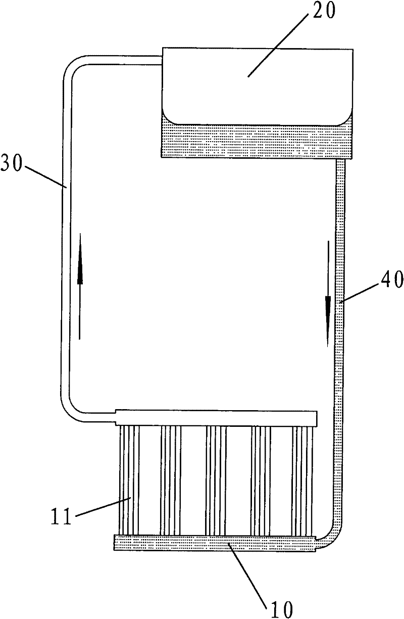
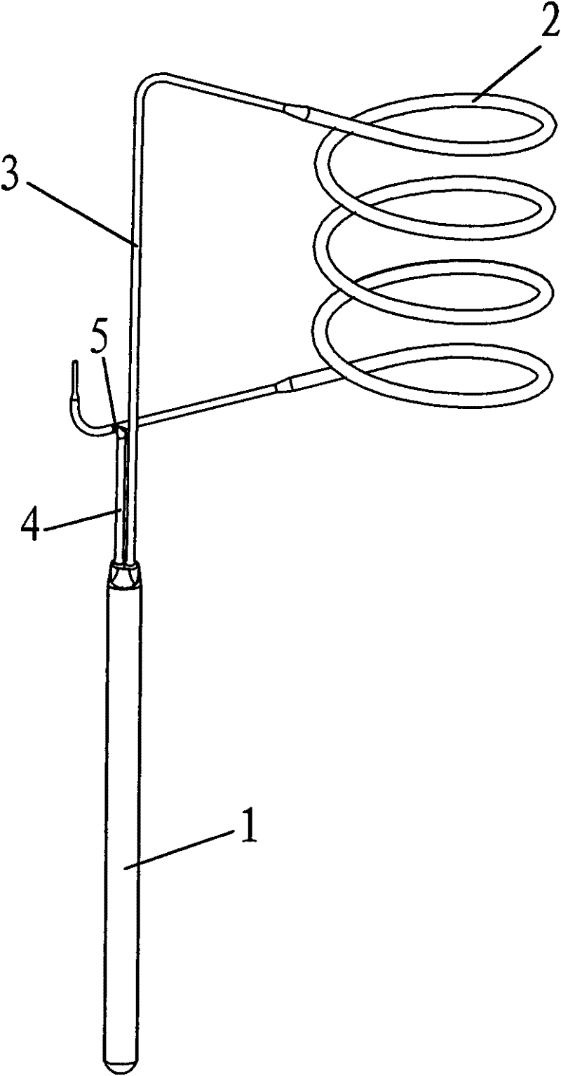
[0044] see image 3 As shown, a loop gravity heat pipe heat transfer device of the present invention mainly includes an evaporator 1 , a condenser 2 , a steam pipeline 3 and a liquid pipeline 4 .

[0045] Among them, please refer to Figure 4 As shown, the evaporator 1 is a tubular evaporator, which is sealed inside and equipped with a working medium 7. The inlet of the steam pipeline 3 is slightly protruded into the top of the evaporator 1, and the outlet of the liquid pipeline 4 passes through the top of the evaporator 1 and is inserted into the Bottom of evaporator 1. The inner surface of the shell of the evaporator 1 can be Figure 5 The smooth surface shown in (a) can also be other structured surfaces to enhance boiling heat transfer and liquid reflux capabilities, such as Figure 5 The straight grooved surface shown in (b), Figure 5 The surface of the spiral groove shown in (c), the spiral groove structure can be continuous or discontinuous, and can also be as Fig...


PUM


Abstract

The invention relates to a loop gravity-assisted heat pipe heat transfer device which mainly comprises an evaporator, a condenser, a steam pipe and a liquid pipe, wherein the evaporator is pipe-shaped, the evaporator is sealed and is filled with a working medium, an inlet of the steam pipe slightly extends into the top of the evaporator, and an outlet of the liquid pipe passes through the top of the evaporator and extends to the bottom of the evaporator; and an outlet of the steam pipe is communicated with the upper part of the condenser, and an inlet of the liquid pipe is communicated with the lower part of the condenser. The loop gravity-assisted heat pipe heat transfer device disclosed by the invention has excellent heat transfer performance and application expandability, can avoid installation difficulty, meets heat transfer requirements of vacuum tube heat collectors with any sizes and has the advantages of reliable structure and manufacturing process and lower cost.

Description

technical field [0001] The invention relates to a high-efficiency heat transfer device in the field of energy utilization, in particular to a novel loop gravity heat pipe heat transfer principle and device. Background technique [0002] The loop gravity heat pipe heat transfer device has universal application in energy utilization, especially in the field of clean energy utilization. [0003] For example, during the construction of the Qinghai-Tibet Railway, due to the large temperature difference between winter and summer, the permafrost layer is formed on the surface in winter, and the surface softens in summer due to heat. resulting in disaster. Here, a two-phase gravity heat transfer device (commonly known as two-phase gravity heat pipe, hot rod) is used to solve the above problems. When the atmospheric temperature is lower than the ground temperature of the permafrost, the gravity heat pipe automatically starts to work, and continuously transmits cold energy from the ...

Claims


Application Information

Patent Timeline
Patent Type & Authority Applications(China)
IPC IPC(8): F28D15/02
CPCF28D15/0266
Inventor 李骥
Owner 北京芯铠电子散热技术有限责任公司
Why Eureka
Try Eureka