Image pickup lens
A camera lens and lens technology, applied in the field of camera lenses, can solve the problems of insufficient power distribution of the first lens and the second lens, insufficient brightness, insufficient miniaturization, etc.
- Summary
- Abstract
- Description
- Claims
- Application Information
AI Technical Summary
Problems solved by technology
Method used
Image

Examples
Embodiment 1)
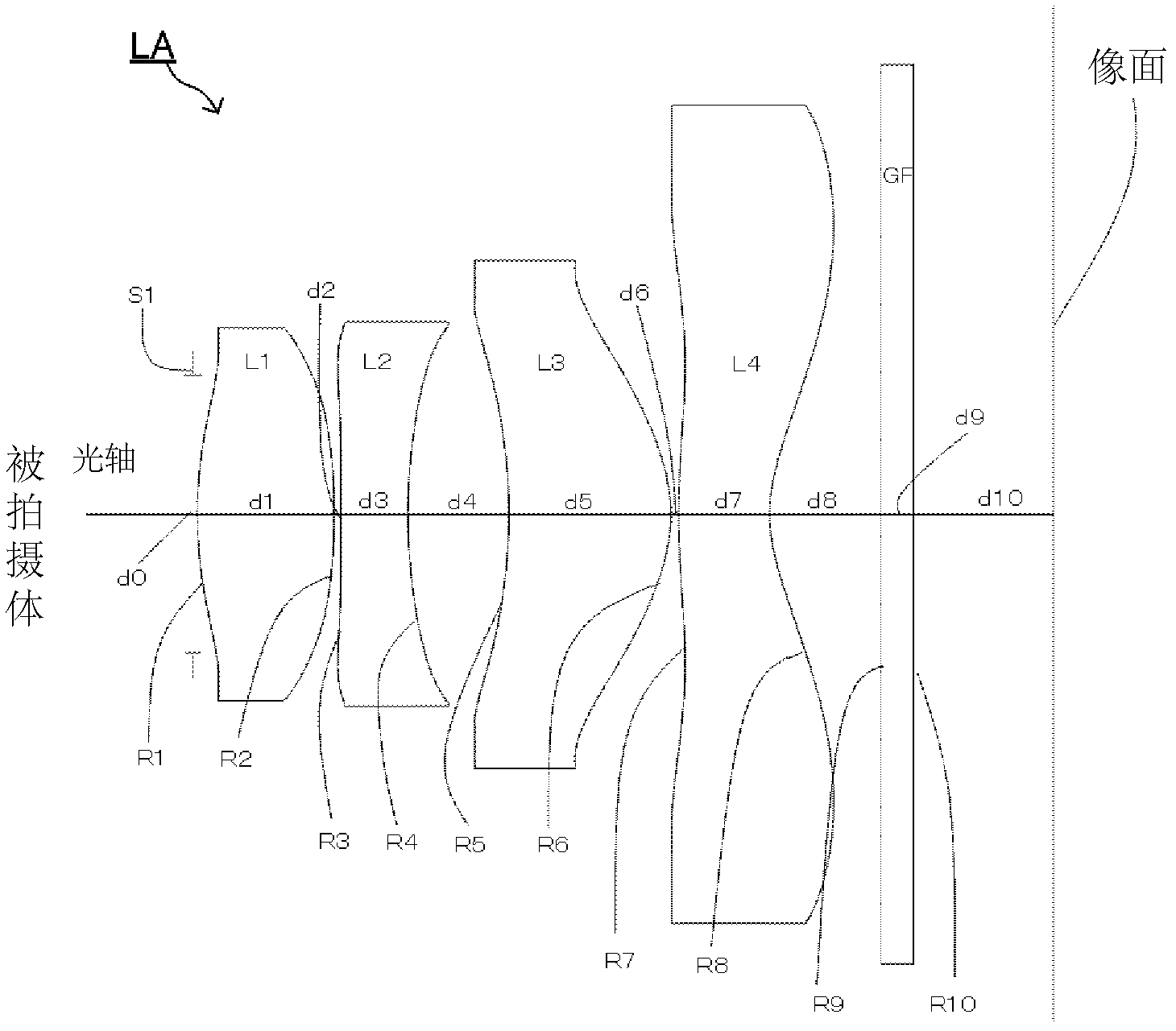
[0254] figure 2 It is a configuration diagram showing the arrangement of the imaging lens LA of the first embodiment. Table 1 shows the radii of curvature R, lens center thickness, or inter-lens distance d, refractive index nd, and Abbe's of each of the object side and image plane side of the first lens L1 to the fourth lens L4 constituting the imaging lens LA of Example 1. The number νd, Table 2 shows the conical coefficient k and aspheric coefficient.
[0255] 【Table 1】
[0256]
[0257] 【Table 2】
[0258]
[0259] In Example 1, as shown in Table 35, conditional expressions (1) to (9) are satisfied.
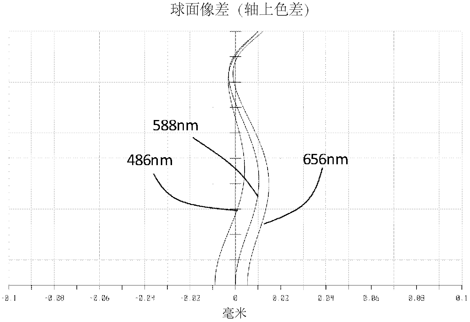
[0260] The spherical aberration (axial chromatic aberration) of the imaging lens LA of Example 1 is image 3 As shown in , the chromatic aberration of magnification is at Figure 4 As shown in , astigmatism and distortion aberration in Figure 5 shown in . From the above results, it can be seen that the imaging lens LA of Example 1 has the characteristics o...
Embodiment 2)
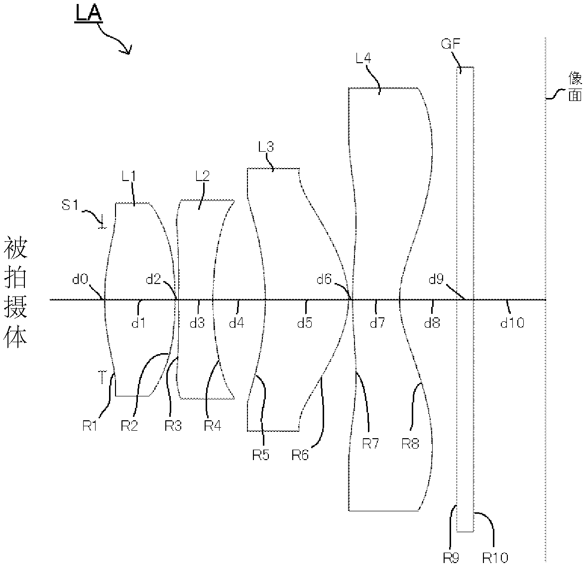
[0262] Figure 6It is a configuration diagram showing the arrangement of the imaging lens LA of the second embodiment. Table 3 shows the curvature radii R, lens center thickness or inter-lens distance d, refractive index nd, and Abbe's of each of the object side and image plane side of the first lens L1 to the fourth lens L4 constituting the imaging lens LA of Example 2. The number νd, Table 4 shows the conical coefficient k and aspheric coefficient.
[0263] 【table 3】
[0264]
[0265] 【Table 4】
[0266]
[0267] In Example 2, as shown in Table 35, conditional expressions (1) to (9) are satisfied.
[0268] The spherical aberration (axial chromatic aberration) of the imaging lens LA of Example 2 is Figure 7 As shown in , the chromatic aberration of magnification is at Figure 8 As shown in , astigmatism and distortion aberration in Figure 9 shown in . From the above results, it can be seen that the imaging lens LA of Example 2 has the characteristics of wide-an...
Embodiment 3)
[0270] Figure 10 It is a configuration diagram showing the arrangement of the imaging lens LA of the third embodiment. Table 5 shows the curvature radii R, lens center thickness, or inter-lens distance d, refractive index nd, and Abbe's radii of each of the first lens L1 to the fourth lens L4 constituting the imaging lens LA of Example 3 on the object side and the image surface side. The number νd, Table 6 shows the conical coefficient k and aspheric coefficient.
[0271] 【table 5】
[0272]
[0273] 【Table 6】
[0274]
[0275] In Example 3, as shown in Table 35, conditional expressions (1) to (9) are satisfied.
[0276] The spherical aberration (axial chromatic aberration) of the imaging lens LA of Example 3 is Figure 11 As shown in , the chromatic aberration of magnification is at Figure 12 As shown in , astigmatism and distortion aberration in Figure 13 shown in . From the above results, it can be seen that the imaging lens LA of Example 3 has the char...
PUM
| Property | Measurement | Unit |
|---|---|---|
| glass transition temperature | aaaaa | aaaaa |
| refractive index | aaaaa | aaaaa |
Abstract
Description
Claims
Application Information
 - R&D
- Intellectual Property
- Life Sciences
- Materials
- Tech Scout
- Unparalleled Data Quality
- Higher Quality Content
- 60% Fewer Hallucinations
Browse by: Latest US Patents, China's latest patents, Technical Efficacy Thesaurus, Application Domain, Technology Topic, Popular Technical Reports.
© 2025 PatSnap. All rights reserved.Legal|Privacy policy|Modern Slavery Act Transparency Statement|Sitemap|About US| Contact US: help@patsnap.com