Optical image capturing lens for bar code reader

A barcode reading and optical technology, applied in the field of optical imaging lenses of barcode readers, can solve the problems of unfavorable manufacturing cost, small field of view, and difficult to manufacture structure.

Inactive Publication Date: 2012-07-04
E PIN OPTICAL IND
View PDF11 Cites 4 Cited by
  • Summary
  • Abstract
  • Description
  • Claims
  • Application Information

AI Technical Summary

Problems solved by technology

However, the field of view (field of angle) of this design is too small, and half of the field of view is only about 23.6°, so it cannot be applied to the optical imaging lens of a small bar code reader machine. The main reason is that The barcode image read by the small barcode reader needs to be closer to the optical imaging lens, and its field angle needs to be larger
[0004] The optical imaging lens used by the barcode reader, such as US Patent Publication No. US 2009 / 0140048, uses a parabolic receiving lens with a diffractive end face to increase the field of view, but its structure is not easy to manufacture, and the parabolic receiving lens has a considerable length. It is not conducive to the demand for miniaturization; Taiwan patent TW M306698 discloses a single-chip optical imaging lens. Although it is simple to manufacture, it requires a longer receiving distance and is not conducive to use
[0005] In order to improve the quality of received images, US Patent No. 5,917,661 discloses the use of two optical lenses, such as Figure 1B , the optical imaging lens 92 includes a biconvex first lens 921, a crescent-shaped second lens 922 with a concave surface on the object side, and a rear aperture 923, so that images can be imaged on the imaging surface 924; The combination of a lens 921 and a crescent-shaped second lens 922 forms an optical imaging lens 92, which adopts stronger refraction power (refraction power) to increase the field of view, but requires a thicker lens to achieve, which is not conducive to Manufacturing cannot be applied to small (thin) barcode readers
[0006] For the design of an optical imaging lens that is beneficial to a high-resolution barcode reader, such as the four-lens optical imaging lens disclosed in U.S. Patent No. 7,477,460 or U.S. Patent Publication No. US2007 / 0097522, its aberration can be obtained Better compensation, but the overall length of the optical imaging lens is still too long, and the number of lenses is large, which is not conducive to the reduction of manufacturing costs

Method used


Image

  • Optical image capturing lens for bar code reader
  • Optical image capturing lens for bar code reader
  • Optical image capturing lens for bar code reader

Examples


no. 1 example

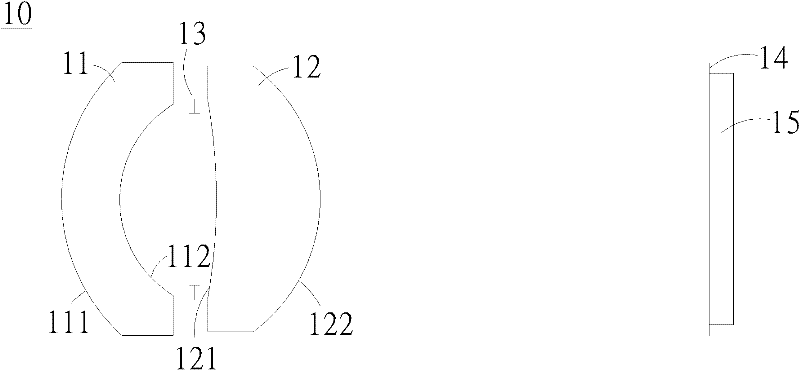
[0051] Please refer to the schematic diagram of the optical imaging lens of the barcode reader according to the first embodiment of the present invention. figure 2 , its light path schematic diagram please refer to image 3 , for the aberration curve of the first embodiment, please refer to Figure 4 . The optical imaging lens 10 of the barcode reader of the first embodiment is arranged along the optical axis from the object side to the image side and includes: a first lens 11 , an aperture stop 13 , a second lens 12 and an image sensor 15 . Wherein, the first lens 11 is a crescent lens, the first lens object-side optical surface 111 is a convex surface, the second lens image-side optical surface 112 is a concave surface, and the first lens object-side optical surface 111 is optically aligned with the first lens image-side optical surface. The surfaces 112 are all aspheric surfaces, satisfying the aspheric surface equation of formula (8); the second lens 12 is a crescent le...

no. 2 example

[0063] For the aberration curve of the second embodiment of the present invention, please refer to Figure 5 The optical imaging lens 10 of the barcode reading machine of the second embodiment is arranged along the optical axis from the object side to the image side and includes: a first lens 11, an aperture stop 13, a second lens 12 and an image sensing element 15 . Wherein, the first lens 11 is a crescent lens, the first lens object-side optical surface 111 is a convex surface, the second lens image-side optical surface 112 is a concave surface, and the first lens object-side optical surface 111 is optically aligned with the first lens image-side optical surface. The surfaces 112 are all aspherical surfaces, satisfying the aspherical surface equation of formula (8); the second lens 12 is a crescent lens, the second lens object side optical surface 121 is a concave surface, and the second lens image side optical surface 122 is a convex surface, and the second lens object side...

no. 3 example

[0075] For the aberration curve of the third embodiment of the present invention, please refer to Figure 6 The optical imaging lens 10 of the barcode reading machine of the third embodiment is arranged along the optical axis from the object side to the image side and includes: a first lens 11, an aperture stop 13, a second lens 12 and an image sensing element 15 . Wherein, the first lens 11 is a crescent lens, the first lens object-side optical surface 111 is a convex surface, the second lens image-side optical surface 112 is a concave surface, and the first lens object-side optical surface 111 is optically aligned with the first lens image-side optical surface. The surfaces 112 are all aspheric surfaces, satisfying the aspheric surface equation of formula (8); the second lens 12 is a crescent lens, the second lens object side optical surface 121 is a concave surface, and the second lens image side optical surface 122 is a convex surface, and the second lens object side optic...


PUM


Abstract

The invention provides an optical image capturing lens for a bar code reader, comprising a first lens of meniscus shape, with its convex surface on the object side and with the object side optical surface and the image side optical surface being aspherical surfaces, a second lens of meniscus shape, with its convex surface on the image side and with the object side optical surface and the image side optical surface being aspherical surfaces, and an image sensor. The image sensor is disposed on an imaging surface after combination of the first lens and the second lens and satisfies the relationship that 2 omega is greater than 62.0 degree and is less than 89.5 degree and TL / D1 / 2 is greater than 1.50 and less THAN 2.20, wherein the 2 omega represents diagonal angle of FOV, TL represents the distance from the object side optical surface of the first lens to the imaging surface, and D1 / 2 is a half of the length of a diagonal line of an effective sensing region of the image sensor. The optical image capturing lens for the bar code reader has shorter length, greater FOV, and excellent aberration correction capability.

Description

technical field [0001] The invention relates to an optical imaging lens for a barcode reading machine, in particular to an optical imaging lens composed of two lenses, which is used for a wide viewing angle required by a small scanning device. Background technique [0002] Generally speaking, the main purpose of a scanning device is to image an image on an electronic image sensor after being read by an optical image reading lens, and the electronic sensor converts the image into an electronic signal and transmits it to the outside world. In order to avoid deformation of the image or to compensate for different wavelengths of light, the design of the optical imaging lens becomes an important key. [0003] For example, U.S. Patent No. 6,147,816 discloses the use of a two-lens optical imaging lens, using two crescent-shaped lenses to form an optical imaging lens, which is used in an image scanner or a facsimile machine; Figure 1A The optical imaging lens 91 includes a first le...

Claims


Application Information

Patent Timeline
Patent Type & Authority Applications(China)
IPC IPC(8): G02B13/18G02B13/00G02B13/06G06K7/10
CPCG02B13/003G02B13/18G06K7/10831H04N5/2254G02B27/0025
Inventor 郭明哲徐三伟
Owner E PIN OPTICAL IND
Why Eureka
Try Eureka