
Micro motor mechanism and driving method thereof

A driving method and motor technology, applied in the direction of microstructure technology, microstructure devices, microstructure devices composed of deformable elements, etc., can solve the problems of high cost and large quantity of piezoelectric ceramics, and achieve low quantity and adjustable The effect of large stroke and large holding force

Active Publication Date: 2012-07-04
SHANGHAI MICRO ELECTRONICS EQUIP (GRP) CO LTD
View PDF4 Cites 3 Cited by
  • Summary
  • Abstract
  • Description
  • Claims
  • Application Information

AI Technical Summary

Problems solved by technology

[0006] The purpose of the present invention is to provide a micro motor mechanism and its driving method to solve the problem that the existing driving mechanism requires a large number of piezoelectric ceramics and the cost is too high

Method used


Image

  • Micro motor mechanism and driving method thereof
  • Micro motor mechanism and driving method thereof
  • Micro motor mechanism and driving method thereof

Examples


Embodiment Construction

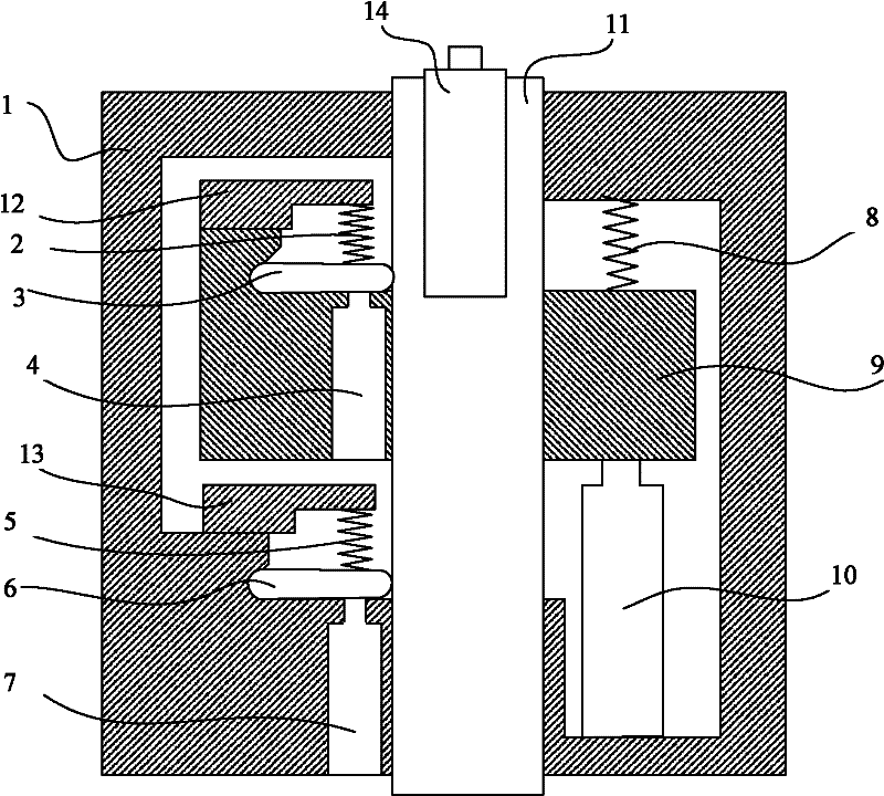
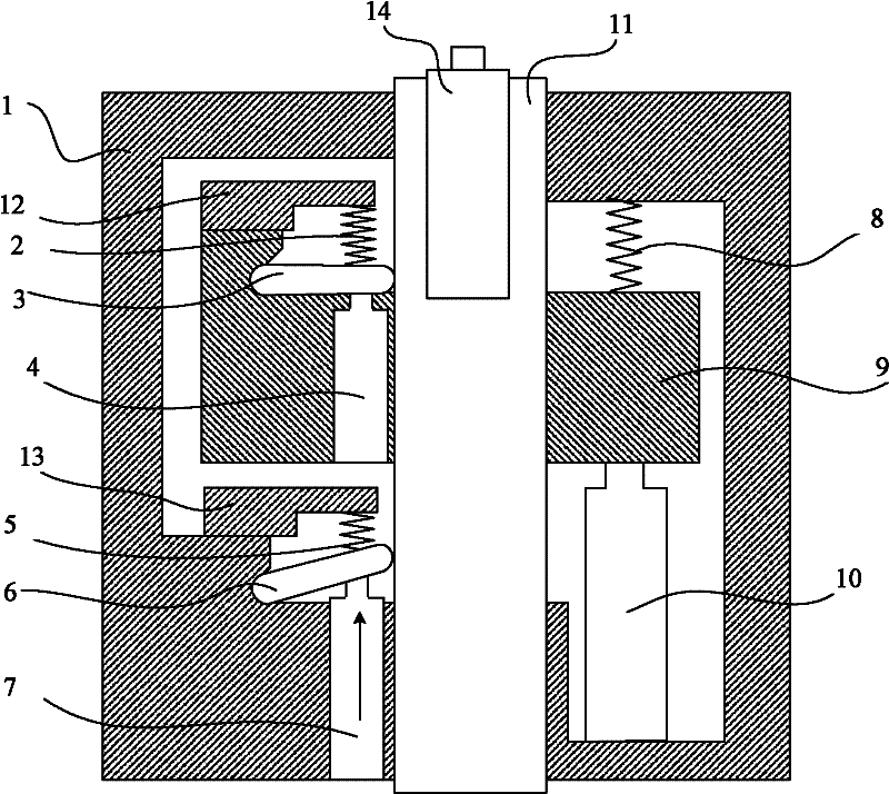
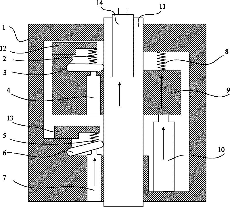
[0057] The micro-motor mechanism and its driving method proposed by the present invention will be further described in detail below in conjunction with the accompanying drawings and specific embodiments. Advantages and features of the present invention will be apparent from the following description and claims. It should be noted that all the drawings are in very simplified form and use imprecise ratios, which are only used for the purpose of conveniently and clearly assisting in describing the embodiments of the present invention.

[0058] The core idea of ​​the present invention is to provide a micro motor mechanism for adjusting the position of the element to be adjusted, the micro motor mechanism includes a frame, a drive shaft arranged in the frame, a primary drive device and a secondary a driving device, the primary driving device drives the driving shaft to move relative to the frame; the secondary driving device is arranged on the top of the driving shaft, and the elem...


PUM


Abstract

The invention discloses a micro motor mechanism, which is used for adjusting the position of an element to be adjusted. The micro motor mechanism comprises a frame, a driving shaft, a primary driving device and a secondary driving device, wherein the driving shaft is arranged in the frame; the primary driving device is used for driving the driving shaft to move relative to the frame; the secondary driving device is arranged on the top of the driving shaft; the element to be adjusted is arranged on the secondary driving device; the element to be adjusted is driven by the secondary driving device to move relative to the top of the driving shaft; thus, a large driving travel can be realized by using the primary driving device, and high resolution can be realized by using the secondary driving; meanwhile, the invention also discloses a driving method of the micro motor mechanism; in the method, large driving travel is realized by using the primary driving device, and high resolution is realized by using the secondary driving; and the method is simple and convenient.

Description

technical field [0001] The invention relates to the field of piezoelectric micro-electromechanical technology in precision machinery, in particular to a high-resolution micro-motor mechanism for adjusting optical elements and a driving method thereof. Background technique [0002] With the improvement of the integration level of semiconductor integrated circuits, the feature size of semiconductor devices is getting smaller and smaller, the requirements for the resolution of the projection optical system in the exposure equipment of advanced lithography machines are also getting higher and higher, and the requirements for the imaging quality of the optical system are also higher. high. The imaging quality of an optical system is usually determined by optical indicators, mainly reflected in various aberrations, such as distortion, spherical aberration or wave aberration. [0003] To improve the imaging quality of the optical system, it is not only required to improve the stab...

Claims


Application Information

Patent Timeline
Patent Type & Authority Applications(China)
IPC IPC(8): G02B26/08B81B3/00
Inventor 王洪尊陈明杰
Owner SHANGHAI MICRO ELECTRONICS EQUIP (GRP) CO LTD
Learn More