
Preparation method of suspension fin

A fin and semiconductor technology, applied in the field of fin structure preparation, can solve the problems of expensive, complex source and drain engineering, etc., and achieve the effects of improved performance, good compatibility, and simple and feasible preparation process

Active Publication Date: 2014-05-07
INST OF MICROELECTRONICS CHINESE ACAD OF SCI
View PDF2 Cites 0 Cited by
  • Summary
  • Abstract
  • Description
  • Claims
  • Application Information

AI Technical Summary

Problems solved by technology

However, there are many problems in using SOI substrates to prepare gate-all-around devices. For example, SOI substrates have self-heating effects and floating body effects, and complex source-drain engineering is required in manufacturing to reduce source-drain parasitic resistance. Generally speaking, SOI substrates The bottom is much more expensive than ordinary bulk silicon substrates

Method used


Image

  • Preparation method of suspension fin
  • Preparation method of suspension fin
  • Preparation method of suspension fin

Examples


Embodiment Construction

[0021] Hereinafter, the present invention is described by means of specific embodiments shown in the drawings. It should be understood, however, that these descriptions are exemplary only and are not intended to limit the scope of the present invention. Also, in the following description, descriptions of well-known structures and techniques are omitted to avoid unnecessarily obscuring the concept of the present invention.

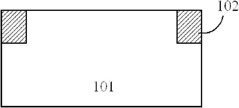
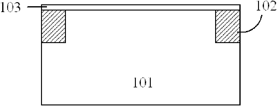
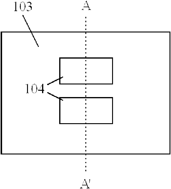
[0022] A schematic diagram of a layer structure according to an embodiment of the invention is shown in the drawing. The figures are not drawn to scale, with certain details exaggerated and possibly omitted for clarity. The shapes of the various regions and layers shown in the figure, as well as their relative sizes and positional relationships are only exemplary, and may deviate due to manufacturing tolerances or technical limitations in practice, and those skilled in the art will Regions / layers with different shapes, sizes, and relative positions can be...


PUM


Abstract

The invention discloses a preparation method of a suspension fin. The preparation method comprises the following steps of: forming a medium layer on a semiconductor substrate; etching the medium layer and the semiconductor substrate so that at least two grooves are formed in the form of being embedded in the semiconductor substrate, and a fin is arranged between each two adjacent grooves; forming a flank by a lateral wall of the fin; etching the semiconductor substrate at the bottoms of the grooves and the fin, so as to form the suspension fin; and forming an isolation medium layer below the fin and the grooves. By using the conventional top-down process based on a reference plane, the preparation method has good compatibility with a CMOS (Complementary Metal Oxide Semiconductor) plane process and is easy to integrate.

Description

technical field [0001] The invention belongs to the technical field of semiconductors, in particular to a method for preparing a fin structure. Background technique [0002] As the integrated circuit industry continues to move forward according to Moore's law, the feature size of CMOS devices continues to shrink. Planar bulk silicon CMOS devices have encountered severe challenges, such as: severe short channel effect (SCE), source-drain leakage current, drain-induced barrier lowering effect (DIBL) and so on. In order to overcome the above problems, various new structure devices have emerged. The gate structure of the device has developed from the initial single gate to double gate (FinFET, fin transistor), multi-gate to the ring gate structure completely surrounding the channel. The gate control ability and the ability to suppress the short channel effect are continuously enhanced with the increase of the number of gates. The preparation of the above new structure devices,...

Claims


Application Information

Patent Timeline
Patent Type & Authority Patents(China)
IPC IPC(8): H01L21/02H01L21/306H01L21/336
Inventor 周华杰宋毅徐秋霞
Owner INST OF MICROELECTRONICS CHINESE ACAD OF SCI
Learn More