[0031] In order to make the above-mentioned objects, features and advantages of the present invention more obvious and easy to understand, the present invention will be further described in detail below in conjunction with the accompanying drawings and specific embodiments.
[0032] In view of this, the purpose of the present invention is to provide an auxiliary converter control device and auxiliary converter system with complete functions and unified interfaces, which can improve the development efficiency of auxiliary converters, reduce research and development costs, and facilitate product development. Unified maintenance.
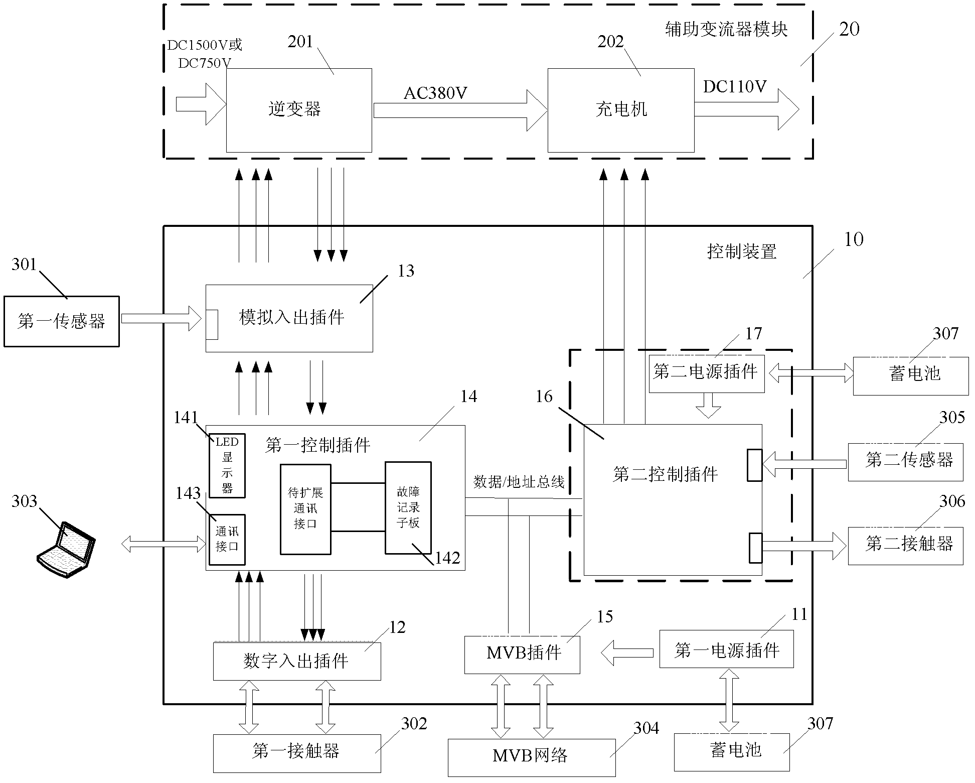
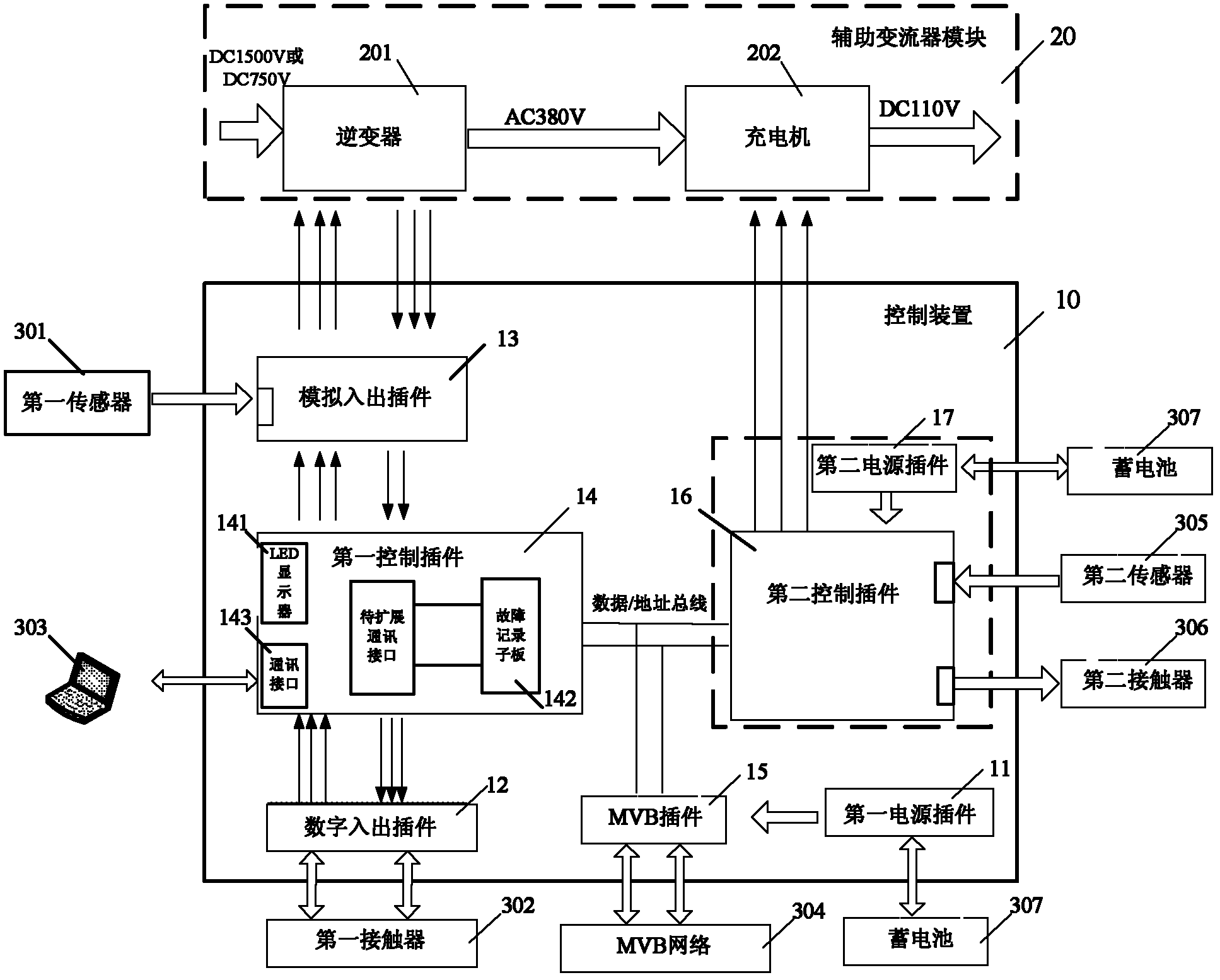
[0033] The control device of the auxiliary converter according to the embodiment of the present invention is used to control the auxiliary converter module. The auxiliary converter module includes an inverter and a charger.
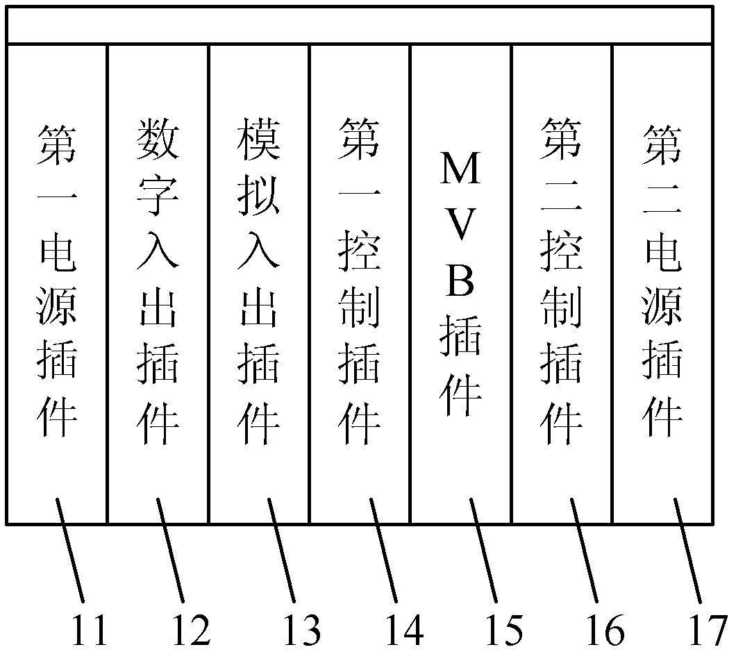
[0034] The control device adopts a plug-in box structure, and the front panel outlet mode includes: a first power plug-in, a digital input/output plug-in, an analog input/output plug-in, a first control plug-in, a multifunctional vehicle bus MVB plug-in, and a second control that are sequentially arranged inside the chassis Plug-in, and second power plug-in.
[0035] The electrical connection between the plug-ins of the control device can be completed through the backplane of the chassis or wiring.
[0036] The analog input and output plug-in is used to collect the analog signal detected by the external first sensor, and send it to the first control plug-in after conditioning; at the same time, it is also used to receive the fault feedback signal output by the inverter, and to The fault feedback signal is transmitted to the first control plug-in after signal isolation and level conversion, and receives the PWM pulse signal output by the first control plug-in, and transmits the pulse signal after signal isolation and level conversion To the inverter.
[0037] The digital input/output plug-in is used to receive the first contactor control signal sent by the first controller plug-in, and after the control signal is digitally processed, it is sent to the external first contactor to control the first contact At the same time, it receives the state signal of the first contactor itself, performs digital processing on the state signal, and sends it to the first control plug-in.
[0038] The first control plug-in is used to perform AD sampling on the signal received from the analog input/output plug-in, send a first contactor control signal to the digital input/output plug-in according to the sampled signal, and receive the digital input/output plug-in The processed status signal is used to determine whether the first contactor is working normally according to the status signal; at the same time, it is also used to receive the fault feedback signal processed by the analog input/output plug-in, and determine the fault feedback signal according to the fault feedback signal. The current working state of the inverter outputs the corresponding PWM pulse signal to the analog input/output plug-in.
[0039] The second control plug-in is used to receive the state signal of the charger detected by the external second sensor, and to adjust and collect the received signal; at the same time, to detect the working state of the second contactor, according to the detection Send a control instruction to the second contactor to control the closing and closing of the second contactor, and realize the control of the charger.
[0040] The multifunctional vehicle bus MVB plug-in is used to provide an external MVB network interface for the control device.
[0041] The first power plug-in is used to provide working power for each plug-in corresponding to the inverter of the auxiliary converter module and the external first sensor.
[0042] The second power plug-in is used to provide working power for each plug-in corresponding to the charger of the auxiliary converter module and the external second sensor.
[0043] The control device according to the embodiment of the present invention includes a first power plug-in, a digital input/output plug-in, an analog input/output plug-in, a first control plug-in, a multifunctional vehicle bus MVB plug-in, a second control plug-in, and a second power supply that are sequentially arranged inside the chassis Plug-in. Through the above plug-ins, the control device can realize the system management, logic judgment, control and fault protection of the auxiliary converter module, and can also provide analog signal processing functions and digital signal processing functions, and is an auxiliary converter module External devices such as sensors provide working power. It can be seen that the control device according to the embodiment of the present invention has perfect functions and unified interfaces, which can improve the development efficiency of auxiliary converters, reduce research and development costs, and facilitate the unified maintenance of products.
[0044] See figure 1 with figure 2 , Respectively are the structural diagram of the control device of the auxiliary converter and the structural block diagram of the auxiliary converter system according to the embodiment of the present invention.
[0045] Such as figure 2 As shown, the auxiliary converter system includes: an auxiliary converter module 20, a control device 10 and external equipment.
[0046] Combine figure 1 with figure 2 As shown, the control device includes: a first power plug-in 11, a digital input/output plug-in 12, an analog input/output plug-in 13, a first control plug-in 14, and an MVB (Multifunction Vehicle Bus) plug-in 15 arranged in sequence inside the chassis , The second control plug-in 16, and the second power plug-in 17.
[0047] Wherein, the auxiliary converter module 20 includes: an inverter 201 and a charger 202. The inverter 202 receives an externally input DC 1500V or DC750V DC voltage, converts it into an AC380V AC voltage, and transmits it to the charger 202; the charger 202 receives the input AC380V AC voltage and outputs a DC110V DC voltage.
[0048] The external equipment includes: a first sensor 301, a first contactor 302, a second sensor 305, a second contactor 306, and so on.
[0049] The first sensor 301 is used to detect the input voltage, input current, output voltage, output current and other analog signals of the inverter 201 of the auxiliary converter module 20. By controlling the closing and closing of the first contactor 302, the working state of the inverter 201 is controlled.
[0050] The second sensor 305 is used to detect signals such as input voltage and input current of the charger 202 of the auxiliary converter module 20. By controlling the closing and closing of the second contactor 306, the working state of the charger 202 can be controlled.
[0051] The first end of the analog input/output plug-in 13 is connected to the first sensor 301, the second end is connected to the inverter 201 of the auxiliary converter module 20, and the third end is connected to the first control plug-in 14.
[0052] The analog input/output plug-in 13 is used to collect and condition the analog signal detected by the first sensor 301, and then send it to the first control plug-in 14; at the same time, it is also used to receive the auxiliary converter The fault feedback signal output by the inverter 201 of the module 20 is transmitted to the first control plug-in 14 after signal isolation and level conversion of the fault feedback signal, and receives the PWM ( Pulse Width Modulation (Pulse Width Modulation) pulse signal, the pulse signal is signal isolated, level converted, and then sent to the inverter 201 of the auxiliary converter module 20.
[0053] It should be noted that the analog input/output plug-in 13 may be provided with 16 analog signal acquisition channels. Of course, in practical applications, the analog input/output plug-in 13 can also be extended to 32, 64 or even more analog signal acquisition channels.
[0054] At the same time, the analog input/output plug-in 13 may be provided with a 12-channel level conversion function, which can realize the level conversion of 12-channel signals. Of course, in practical applications, the analog input/output plug-in 13 can also be provided with more channels of level conversion functions.
[0055] One end of the digital input/output card 12 is connected to the first contactor 302, and the other end is connected to the first control card 14 for receiving the first contactor control signal sent by the first controller card 14 After the control signal is digitally processed, it is sent to the first contactor 302 to control the pull-in and disconnection of the first contactor 302; at the same time, it receives the state signal of the first contactor 302 to control After the status signal is digitally processed, it is sent to the first control plug-in 14.
[0056] The first control plug-in 14 is used for AD sampling the signal received from the analog input/output plug-in 13, and sends a first contactor control signal to the digital input/output plug-in 12 according to the sampled signal, and receives the The state signal of the first contactor 302 processed by the digital input/output plug-in 12 is used to determine whether the first contactor 302 is working normally according to the state signal; at the same time, it is also used to receive the fault feedback processed by the analog input/output plug-in 13 Signal, according to the fault feedback signal, determine the current working state of the inverter 201 of the auxiliary converter module 20, and output a corresponding PWM pulse signal to the analog input/output plug-in 13.
[0057] It should be noted that the first contactor control signal sent by the first controller plug-in 14 is a 5V signal, and the digital input/output plug-in 12 performs digital processing on the control signal specifically: isolating and converting the 5V signal to 110V signal. Correspondingly, the digital processing of the status signal by the digital input/output plug-in 12 specifically includes: isolating and converting a 110V signal into a 5V signal.
[0058] Specifically, the digital input/output plug-in 12 can provide 16 input channels from 110V to 5V, and 8 output channels from 5V to 110V. Of course, in actual needs, the digital input/output plug-in 12 can also be digitally expanded according to the needs of the system.
[0059] The second control plug-in 16 is connected to the charger 202 of the auxiliary converter module 20 and is used to implement all control functions of the charger 202.
[0060] Specifically, the control of the charger 202 by the second control plug-in 16 includes: receiving the state signal (such as input voltage, input current, etc.) of the charger 202 detected by the second sensor 305, and receiving The received signal is adjusted and collected; at the same time, the working state of the second contactor 306 is detected, and control instructions are sent to the second contactor 305 according to the detected signal to control the second contactor 305 Closed and closed to realize functions such as logic control and fault protection of the charger 202.
[0061] It should be noted that, in the embodiment of the present invention, the first control plug-in 14 and the second control plug-in 16 are the core of the entire control device 10, and are used to implement logic control, fault protection, and reverse control of the entire auxiliary converter system. Variable control and other functions.
[0062] Such as figure 2 As shown, the first control plug-in 14 and the second control plug-in 16 are connected through a data/address bus, so that the first control plug-in 14 and the second control plug-in 16 can access the first control plug-in through the data/address bus The dual-port RAM (Random Access Memory) on 14 performs data transfer.
[0063] Preferably, an LED display 141 may be provided on the panel of the first control plug-in 14 for real-time display of the current time, date, vehicle number, software version number, operating parameters of the auxiliary converter module 20, or the auxiliary The fault code of the converter module 20 failure.
[0064] The LED display 141 may be an LED digital tube.
[0065] The operating parameters of the auxiliary converter module 20 include: output current of each phase, input current, output voltage of each phase, output frequency, etc.
[0066] In the embodiment of the present invention, through the LED display 141, various parameters and information of the auxiliary converter system can be observed in real time, and the working status of the system can be understood in real time.
[0067] Preferably, the first control plug-in 14 may also include a fault recording sub-board 142 for automatically storing and recording fault information of the auxiliary converter module 20. Wherein, the fault information may include: fault code, date and time when the fault occurred, and related environmental data.
[0068] It should be noted that the first control plug-in 14 may adopt a fixed-point DSP (Digital Signal Processing, digital signal processing) processor, and the fault recording sub-board 142 may adopt an ARM9 microprocessor, thereby using a programmable logic device ( Complex Programmable Logic Device (CPLD) realizes the address decoding function of the system circuit, and cooperates with the DSP processor to complete the fault reset logic.
[0069] Preferably, the first control plug-in 14 is provided with a communication interface 143, so that an operator can connect a data processing device 303 to the first control plug-in 14 through the communication interface 143 to realize the data processing device 303 and the first control plug-in 14 The first control plug-in 14 communicates for data query, analysis and processing.
[0070] The data processing device 303 may be a computer, a notebook, such as an IBM compatible computer, etc. Correspondingly, the communication interface 143 may be a USB2.0 and Ethernet interface.
[0071] Preferably, the first control plug-in 14 is also provided with a communication interface to be expanded, which may be an Ethernet communication interface or a universal serial interface. The operator can use the host computer to perform operation monitoring, fault recording, program downloading, etc. of the auxiliary converter module through the Ethernet or universal serial interface through the communication interface to be expanded.
[0072] The MVB plug-in 15 is used to provide a network interface for the control device. The control device is connected to the external MVB network 304 through the MVB plug-in 15 to realize the network control of the auxiliary converter module 20.
[0073] Thus, the fault information, fault status, and working status information of the auxiliary converter module 20 can be transmitted to the train network control system through the MVB network 304, which together constitute the real-time network control and monitoring system of the entire train.
[0074] The external device may also include a battery 307, such as figure 2 As shown, the storage battery 307 is respectively connected to the first power plug-in 11 and the second power plug-in 17 to provide input power for the first power plug-in 11 and the second power plug-in 17.
[0075] The first power plug-in 11 is used to provide working power for each plug-in corresponding to the inverter 201 of the auxiliary converter module 20 and the external first sensor 302 and other equipment, such as ±24V, ±15V, 5V, etc. . The plug-ins corresponding to the inverter 202 of the auxiliary converter module 20 include the analog input/output plug-in 13, the first control plug-in 14, and the digital input/output plug-in 15.
[0076] The second power plug-in 17 is used to provide working power for each plug-in corresponding to the charger 202 of the auxiliary converter module 20 and the external second sensor 305 and other devices, such as ±24V, ±15V, 5V power supply, etc. The plug-ins corresponding to the charger 202 of the auxiliary converter module 20 include the second control plug-in 16.
[0077] For the control device of the auxiliary converter described in the foregoing embodiments of the embodiments of the present invention, the structure of each plug-in can be a 6U standard plug-in.
[0078] In the control device, the electrical connection between the plug-ins can be completed through the backplane of the chassis or wiring.
[0079] It should be noted that the control device described in the embodiment of the present invention adopts a plug-in box structure, signals are inserted or output from the front panel of each plug-in, and the signal is transmitted between the chassis and the auxiliary converter module through a shielded cable, so as to achieve the Auxiliary converter module management, logic control, and display functions.
[0080] The control device described in the embodiment of the present invention has an error-proof design. Specifically, each plug-in is provided with a corresponding error-proof tooth, so that the control device is convenient to use and maintain. The control device can be applied to control systems of auxiliary converter modules such as rectifiers and DC/DC converters. The control device has good scalability and can adapt to some special needs of different users.
[0081] Further, the control device according to the embodiment of the present invention has low cost and is suitable for mass production.
[0082] The control device of the auxiliary converter and the auxiliary converter system provided by the present invention are described in detail above. In this article, specific examples are used to explain the principles and implementation of the present invention. The description of the above embodiments It is only used to help understand the method and core idea of the present invention; at the same time, for those of ordinary skill in the art, according to the idea of the present invention, there will be changes in the specific implementation and the scope of application. In summary, the content of this specification should not be construed as limiting the present invention.