Parallel three-phase grid-connected inverter adopting mutual reactors and control method for three-phase grid-connected inverter

A technology of a three-phase inverter and control method, applied in the direction of irreversible DC power input conversion to AC power output, electrical components, output power conversion devices, etc., can solve the problem of large volume and weight, narrow application range, and complex control and other problems to achieve the effect of solving uneven flow, reducing volume and weight, and suppressing zero-sequence circulation

Active Publication Date: 2012-07-04
HARBIN INST OF TECH
View PDF6 Cites 19 Cited by
  • Summary
  • Abstract
  • Description
  • Claims
  • Application Information

AI Technical Summary

Problems solved by technology

[0009] In order to overcome the shortcomings of traditional parallel-connected grid-connected inverters such as large volume and weight, high cost, low efficiency, narrow application range, complex control,

Method used


Image

  • Parallel three-phase grid-connected inverter adopting mutual reactors and control method for three-phase grid-connected inverter
  • Parallel three-phase grid-connected inverter adopting mutual reactors and control method for three-phase grid-connected inverter
  • Parallel three-phase grid-connected inverter adopting mutual reactors and control method for three-phase grid-connected inverter

Examples


specific Embodiment approach 1

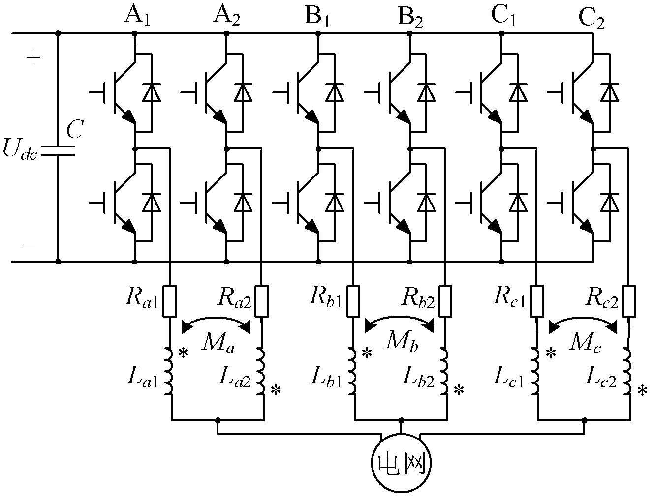
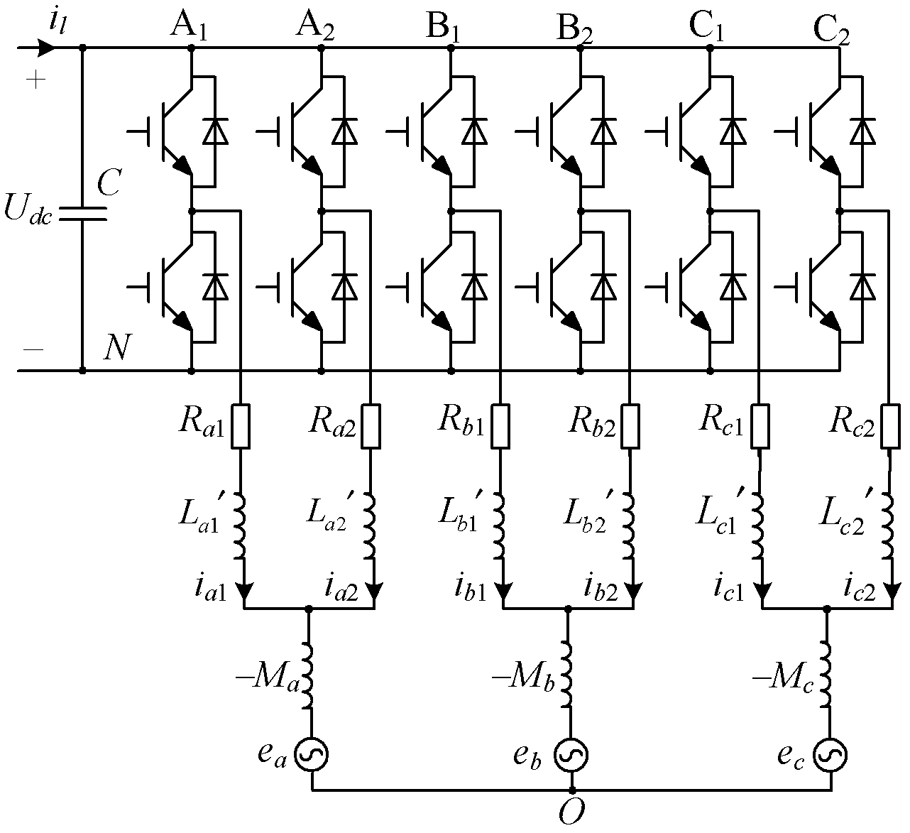
[0027] Specific implementation mode one, see figure 1 , 2 and 3 illustrate this embodiment. The parallel-connected three-phase grid-connected inverter using coupling reactor described in this embodiment is composed of two sets of three-phase grid-connected inverters with the same structure and three sets of coupling reactors. Two sets of three-phase grid-connected inverters with the same structure share a common DC bus, and capacitors are connected in parallel on the DC bus; the two sets of three-phase grid-connected inverters with the same structure are connected in parallel with each other, and the two sets of three-phase grid-connected In the phase grid-connected inverter, the two AC signal output terminals belonging to the same phase are respectively connected together through a set of coupling reactors and connected to the power grid.

[0028] The power switches in the two sets of three-phase grid-connected inverters with the same structure described in this embodiment c...

specific Embodiment approach 2

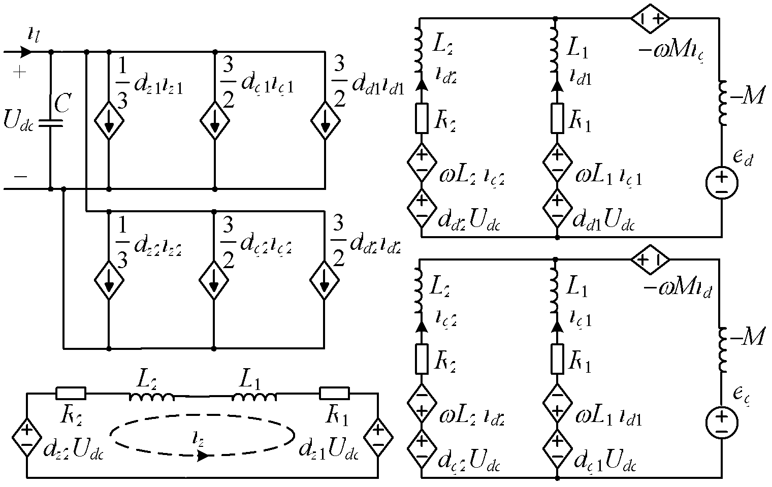
[0040] Specific implementation mode two, see Figure 4 This embodiment will be described. This embodiment describes the control method for the parallel-connected three-phase grid-connected inverter using coupling reactors described in the first embodiment, the control method is: using the DC bus voltage signal obtained by voltage sensor measurement as The DC voltage feedback value Udc, the difference between the DC bus voltage reference value Udcref and the DC voltage feedback value Udc are input to the voltage loop PI controller, and the idref is obtained after being processed by the voltage loop PI controller, and the idref is obtained after weight distribution. Two current given values ​​id1ref, id2ref, the two current given values ​​id1ref, id2ref respectively serve as the current given values ​​of the d-axis current loop controllers of two sets of grid-connected three-phase inverters;

[0041] At the same time, current sensors are used to measure the three-phase current ...

specific Embodiment approach 3

[0045]Specific Embodiment 3. This embodiment is a further limitation of the control method described in Specific Embodiment 2. In this embodiment, the process of weight distribution is: perform current weighting according to the power capacity of two sets of three-phase inverters Allocation, if the power capacity of the two sets of three-phase inverters is equal, the equivalent allocation is carried out, that is, i d1ref = i d2ref =0.5i dref ; If the power capacities of the two sets of three-phase inverters are not equal, they will be distributed in proportion according to the power capacity, that is, i d1ref =j·i dref , i d2ref =(1-j)i dref , j is the power capacity ratio of two sets of three-phase inverters.


PUM


Abstract

The invention discloses a parallel three-phase grid-connected inverter adopting mutual reactors and a control method for the three-phase grid-connected inverter, and belongs to the technical field of power grid inversion. The inverter overcomes the shortcomings of large volume, high weight, high cost, low efficiency, narrow application range, control complexity, low reliability and the like of the conventional parallel grid-connected inverter. According to the inverter, two sets of three-phase grid connected inverters are connected in parallel, and a capacitor is connected in parallel with a direct current bus which is shared by the two sets of three-phase grid connected inverters; and the two in-phase alternating current signal output ends of the two sets of three-phase grid-connected inverters are connected together after passing through a set of mutual reactor respectively, and are connected with a power grid. According to the three-phase grid-connected inverter, the two sets of three-phase grid-connected inverters with the same structure are coupled with each other by the mutual reactors; and for each three-phase grid-connected inverter, a d-axis component and a q-axis component are coupled with each other, and in order to eliminate the influence, a feed-forward decoupling control strategy and a current loop are adopted in the control method.

Description

technical field [0001] The invention belongs to the technical field of grid inverter, and in particular relates to a three-phase grid-connected inverter. technical background [0002] With the enhancement of people's awareness of environmental protection and the increasing shortage of energy, the new energy industry represented by wind energy and solar energy has made great progress. In order to transmit the electrical energy converted from wind energy, solar energy, etc. to the grid, it is usually necessary to convert it into electrical energy whose amplitude, frequency, and phase are consistent with the grid, so as to realize the grid-connected operation of the system. In order to increase the power level of grid-connected inverters, reduce production costs, and improve system reliability, the parallel operation of inverters has received extensive attention. Under the condition of not increasing the current stress of a single power switch, the total current can be multipl...

Claims


Application Information

Patent Timeline
IPC IPC(8): H02M7/48H02M7/537
Inventor 李瑞徐殿国朱辉
Owner HARBIN INST OF TECH
Why Eureka
Try Eureka