Multi-roll straightening machine

A technology of multi-roller straightening and frame, applied in the field of multi-roller leveling machine, can solve the problems of prolonged roll changing time, difficult maintenance and operation, complicated structure, etc., to achieve easy maintenance and replacement, save auxiliary time, simple and reliable operation Effect

Active Publication Date: 2013-11-13
MCC CAPITAL ENGINEERING & RESEARCH +1
View PDF9 Cites 3 Cited by
  • Summary
  • Abstract
  • Description
  • Claims
  • Application Information

AI Technical Summary

Problems solved by technology

However, its structure is relatively complicated, and the spring is prone to failure during use, and it is not easy to loosen the base of the upper roller system and the upper movable beam smoothly, thus prolonging the time for changing rollers
[0004] 2. The multi-roll straightening machines commonly used in China are all equipped with side roll adjustment devices, which can flexibly adjust the height of the side rolls to improve the shape of the plate and improve the straightening accuracy. However, because the existing side roll adjustment devices are set at The inside of the rack brings great difficulties to the maintenance work
[0005] 3. The roll changing hydraulic cylinder of the existing straightening machine is generally arranged under the frame, and the maintenance operation is very difficult
When changing the roll, the old roll is pulled out of the frame by the roll changing hydraulic cylinder, and its spline teeth come out of the spline sleeve; when the new roll is inserted, it is easy to cause the position of each spline tooth to not match the spline sleeve, resulting in a new The roll cannot be inserted directly and accurately, which prolongs the time for changing the roll and reduces the production efficiency

Method used


Image

  • Multi-roll straightening machine
  • Multi-roll straightening machine
  • Multi-roll straightening machine

Examples


Embodiment Construction

[0034] In order to have a clearer understanding of the technical features, purposes and effects of the present invention, the specific implementation manners of the present invention will now be described with reference to the accompanying drawings.

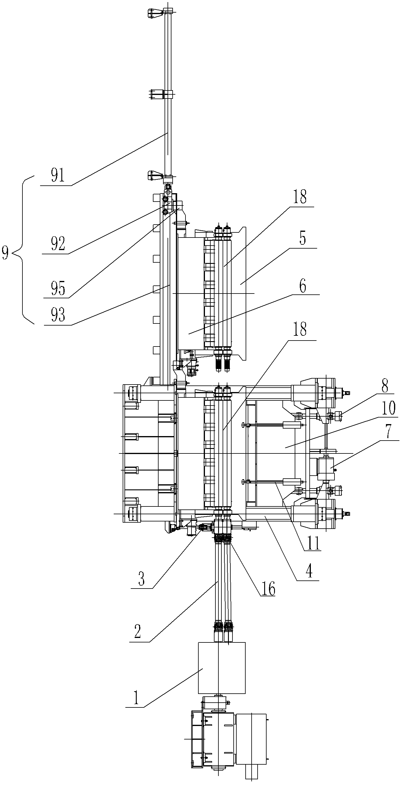
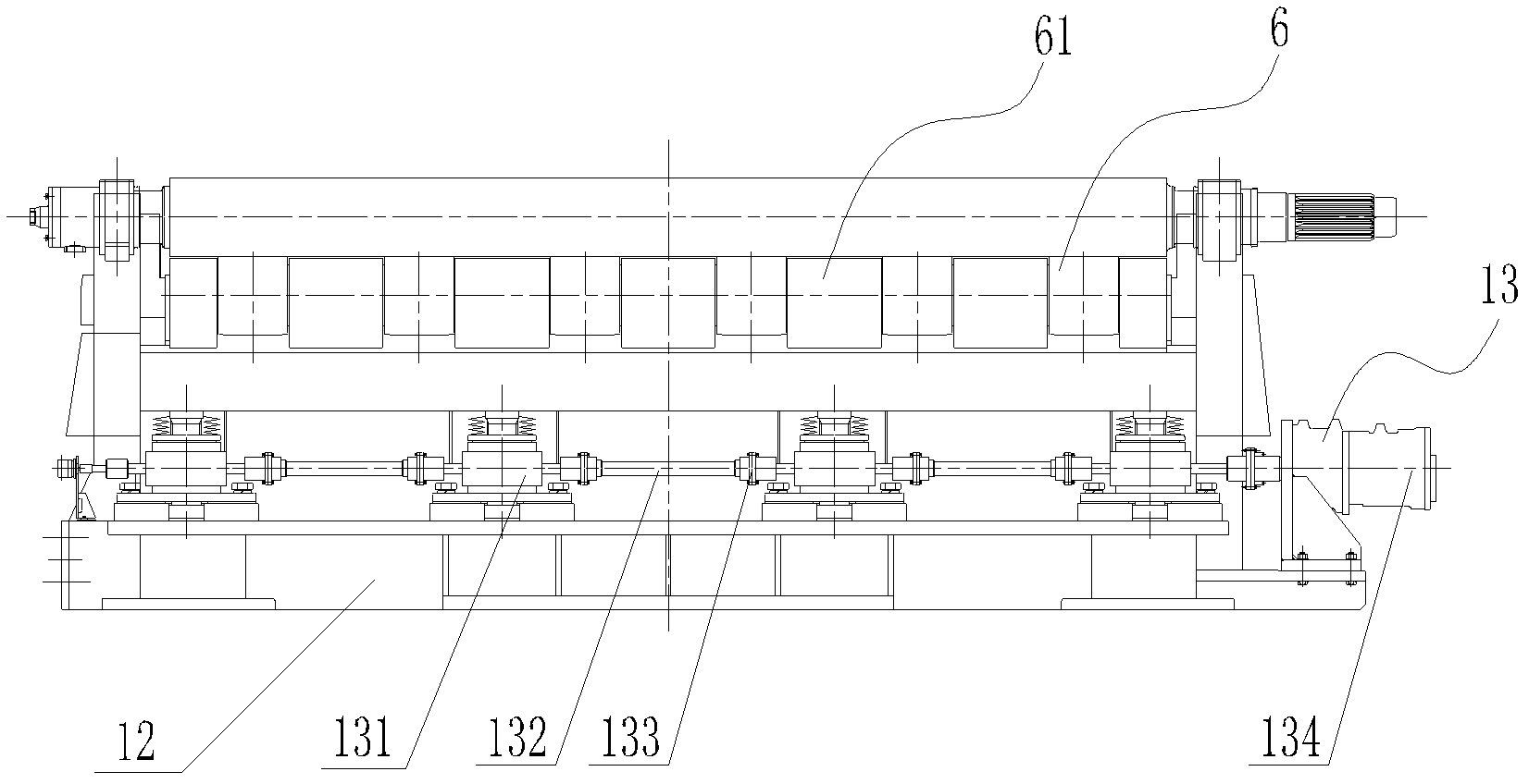
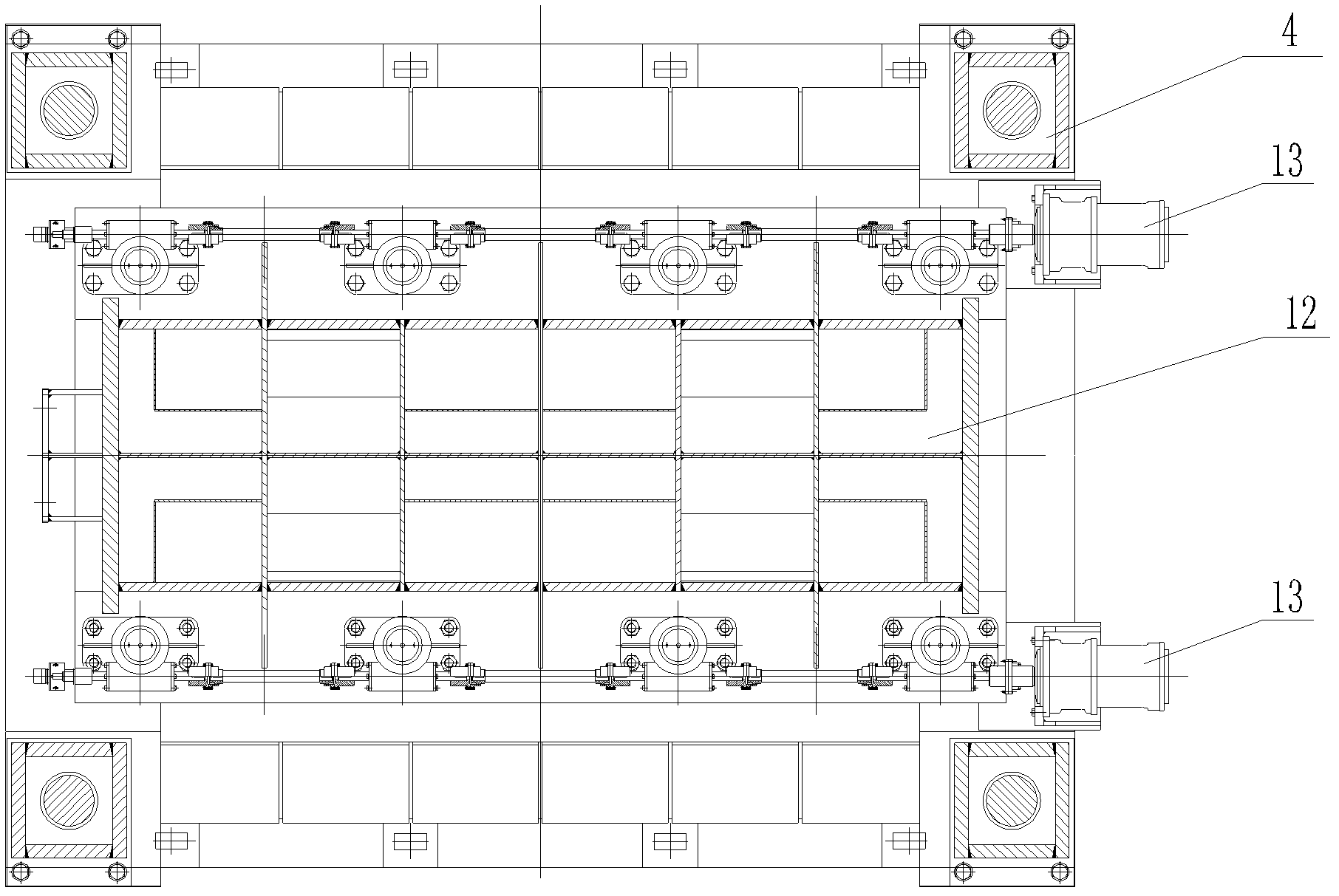
[0035] Please refer to figure 1 , figure 2 with image 3 , is a schematic structural view of the multi-roll leveler of the present invention; a schematic structural view of the front view and a schematic view of the top view of the side roll lifting device of the present invention. As shown in the figure, the multi-roll straightening machine proposed by the present invention includes a main transmission mechanism 1, a universal joint shaft 2, a joint shaft holding mechanism 3, a frame 4, an upper roller device 5, a lower roller device 6, a pressing Mechanism 7, roll bending and balancing mechanism 8 and roll changing device 9, upper movable beam 10 is installed on frame 4, upper roller device 5 is supported by upper movable be...


PUM


Abstract

The invention discloses a multi-roll straightening machine, which comprises a main transmission mechanism, a universal connecting shaft, a connecting shaft holding mechanism, a stand, an upper roll device, a lower roll device, a pressing mechanism, a bending roll and balance mechanism and a roll change device, wherein the stand is provided with an upper movable cross beam; the upper roll device is supported by the upper movable cross beam; the upper roll device is connected with the upper movable cross beam through a plurality of clamping devices; the lower roll device comprises a lower row straightening roll, a lower roll device pedestal and side rolls; the side rolls are arranged on the two sides of the lower row straightening roll; the lower roll device is supported through the lower roll device pedestal; the side part of the lower roll device pedestal is provided with a side roll lifting device; and the side roll lifting device is pressed against the side rolls oppositely. The multi-roll straightening machine is applied to the field of straightening of medium and thick plates, has a compact structure, high rigidity and high roll change speed, can realize reversible reciprocating straightening, has good plate shape correction and can particularly meet the requirement of straightness of high-strength steel plates of thin specification.

Description

technical field [0001] The invention relates to a multi-roll straightening machine, in particular to a multi-roll straightening machine for improving the shape of a medium-thick plate and capable of quickly changing rolls. Background technique [0002] As we all know, the straightening machine is the key equipment in the finishing process of medium and thick plates. The straightening machine squeezes and straightens steel materials through straightening rollers. For example, the Chinese Utility Model Patent (Notice No. CN2309192Y) discloses a medium and thick plate thermal straightening machine, including a motor, a shaft coupling, a reducer, a distribution box, a crosshead universal joint shaft, a frame, and a pressing device , unloading device, upper roller device, lower roller device, etc. The lower roller device includes the lower row of straightening rollers, the base of the lower roller device, and the side rollers. The four threaded pull rods are used to pre-tighten ...

Claims


Application Information

Patent Timeline
Patent Type & Authority Patents(China)
IPC IPC(8): B21D1/02
Inventor 马晓明贾庆春胡晓军胡典章岳杰陆志贤李亚军郝建伟尹海元张振张礼明
Owner MCC CAPITAL ENGINEERING & RESEARCH
Why Eureka
Try Eureka