

Crystallizer for continuous steel casting
A mold and steel casting technology, applied in the field of continuous steel casting equipment, can solve the problems of insufficient tensile strength of billets, unstable cooling temperature, slow cooling speed, etc., to avoid leakage accidents, good thermal conductivity, and improve billet drawing effect of speed
Inactive Publication Date: 2012-07-11
TAIYUAN UNIVERSITY OF SCIENCE AND TECHNOLOGY
View PDF4 Cites 9 Cited by
- Summary
- Abstract
- Description
- Claims
- Application Information
AI Technical Summary
Problems solved by technology
Its disadvantage is that the cooling speed is slow and the cooling temperature is unstable, which often leads to insufficient tensile strength of the billet and causes leakage accidents.
Method used
View moreImage
Smart ImageViewing Examples

Examples
Embodiment Construction
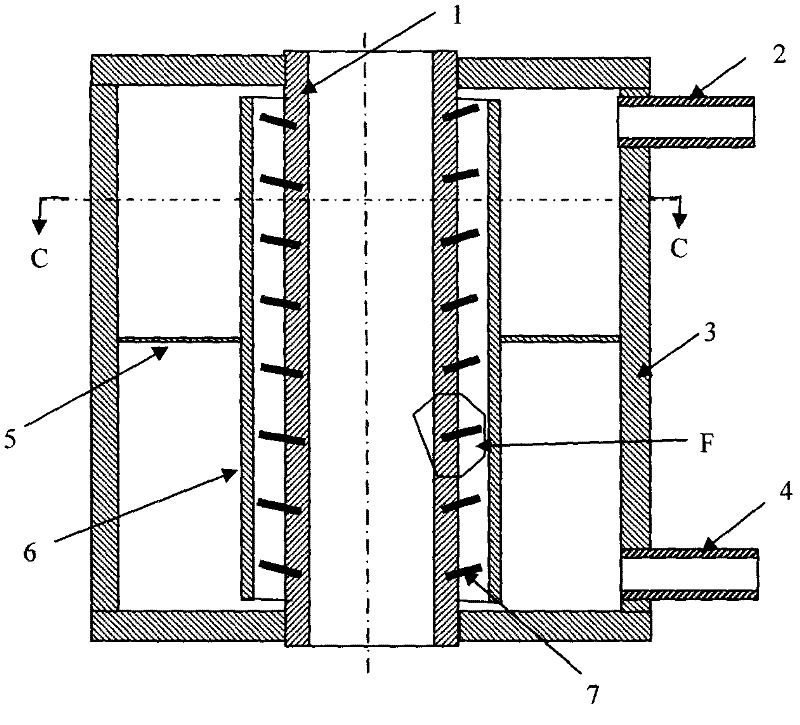
[0011] Such as image 3 , as shown in 4 and 5, start the cooling system 5-10 minutes before continuous casting, that is, connect the inlet pipe 4 to inject high-pressure cooling water, and at the same time, open the outlet pipe 2 to allow the high-pressure cooling water to circulate and cool through the crystallizer. Started continuous casting of molten steel for continuous steel casting production.
Login to View More PUM
 Abstract
A crystallizer for continuous steel casting belongs to the field of continuous steel casting equipment and comprises a crystallizing tube, a casing, an inlet tube and an outlet tube. The crystallizer is characterized in that n heat tubes are mounted on the outer wall of the crystallizing tube, wherein the n is the positive integer. Further, each heat tube is a hollow tube with two ends closed, a heat transfer medium is filled in a cavity of the hollow tube, an external thread is formed at one end of the heat tube, the heat tube is connected with a thread hole on the outer wall of the crystallizing tube through the external thread, fine copper powder is filled at the bottom of the thread hole, and the heat tubes mounted on the outer wall of the crystallizing tube are oblique upwards and form included angle ranging from 8 degrees to 12 degrees horizontally with the outer wall of the crystallizing tube. The crystallizer has the advantages that heat dissipation capacity of the crystallizing tube is improved, casting speed is increased, cool forming of steel billets is facilitated, tensile strength of the steel billets is enhanced, and breaking-out is avoided.
Description
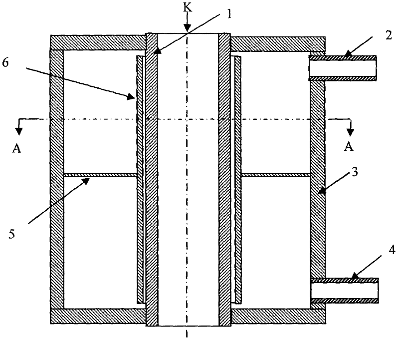
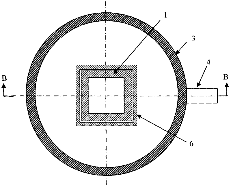
technical field [0001] The invention belongs to the field of continuous steel casting equipment, in particular to a crystallizer for continuous steel casting. Background technique [0002] Continuous steel casting is a production technology of continuous casting of molten steel, which has been widely used in countries all over the world. The heat transfer mode of the continuous steel casting machine crystallizer is a key technology that affects the production efficiency and product quality of steel casting. At present, the crystallizer at home and abroad uses a circulating water cooling system, and the structure of the crystallizer is as follows: figure 1 and 2 As shown, this crystallizer includes a crystallization tube 1 , an outlet tube 2 , a shell 3 , a partition 5 , and a casing 6 . During continuous steel casting, the molten steel enters the crystallization tube 1 from the molten steel injection port K, and the cooling water enters the cavity of the crystallizer from...
Claims
Login to View More Application Information
Patent Timeline
 Patent Type & Authority Applications(China)
IPC IPC(8): B22D11/04B22D11/055
Inventor 王宥宏虞明香王洋丽王荣峰李秋书崔小朝
Owner TAIYUAN UNIVERSITY OF SCIENCE AND TECHNOLOGY