Combined blow-molding tray

A combination and tray technology, applied in rigid containers, containers, packaging, etc., can solve problems such as loosening of bolt holes and screw rods, complex manufacturing process of inserting rod devices, and damage to tray structures, so as to save transportation space and facilitate assembly and disassembly. The solution process is simple and fast, and the effect of manufacturing low energy consumption

Inactive Publication Date: 2012-07-11
张然
View PDF8 Cites 8 Cited by
  • Summary
  • Abstract
  • Description
  • Claims
  • Application Information

AI Technical Summary

Problems solved by technology

The manufacturing process of the inserting rod device is complicated, the cost is high, and the inserting rod has a slender structure and is easy to break. Once the inserting rod is broken, the entire tray cannot be used
The Chinese Utility Model Patent Publication No. CN201971244U discloses a combined pallet composed of multiple panels arranged in parallel. The pallet panel and the legs are connected by bolts. The different materials of the screw rod and the bolt hole may cause damage to the bolt during use. The hole and the screw thread are loose, causing damage to the tray structure and making it unusable

Method used


Image

  • Combined blow-molding tray
  • Combined blow-molding tray
  • Combined blow-molding tray

Examples


Embodiment 1

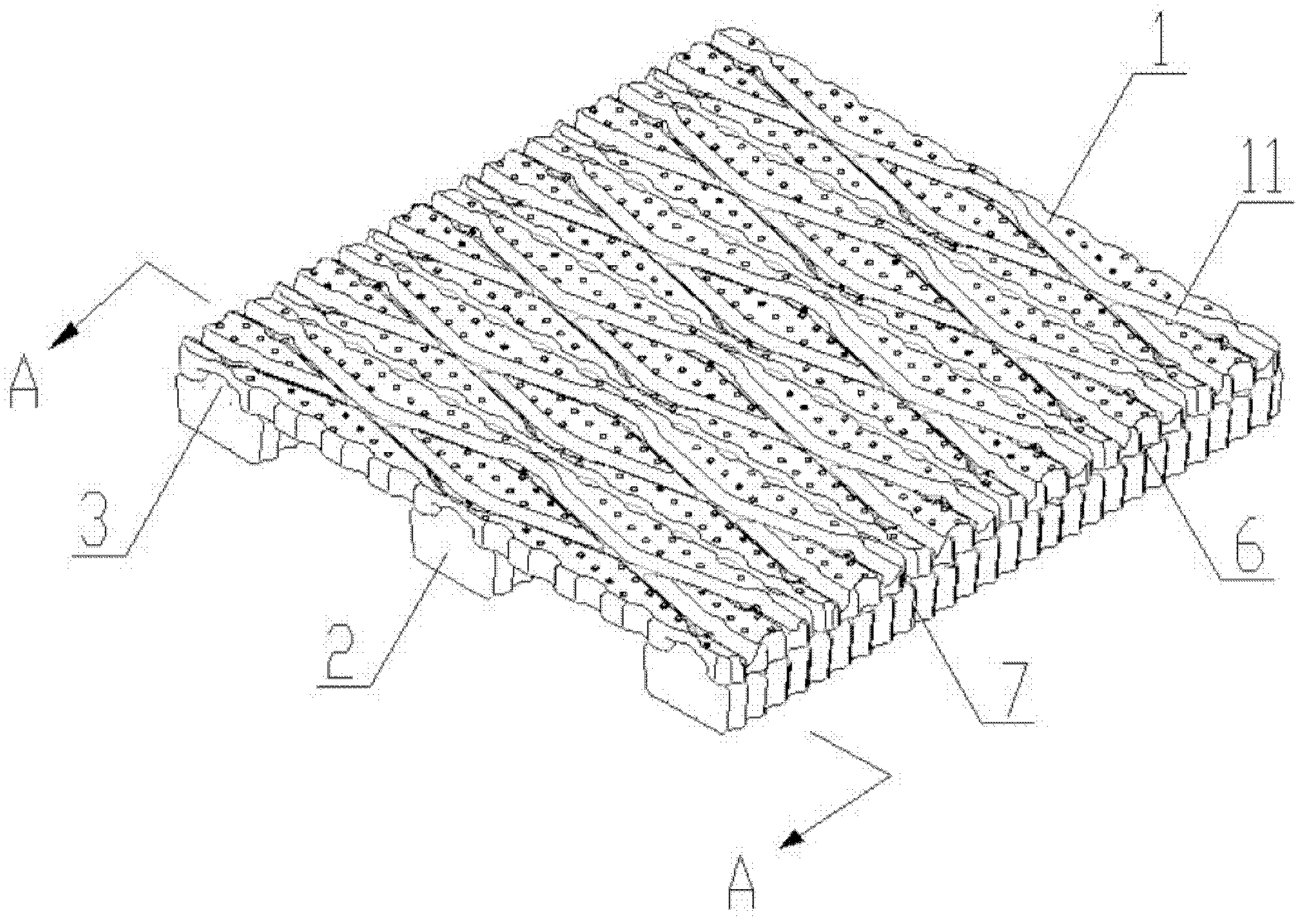
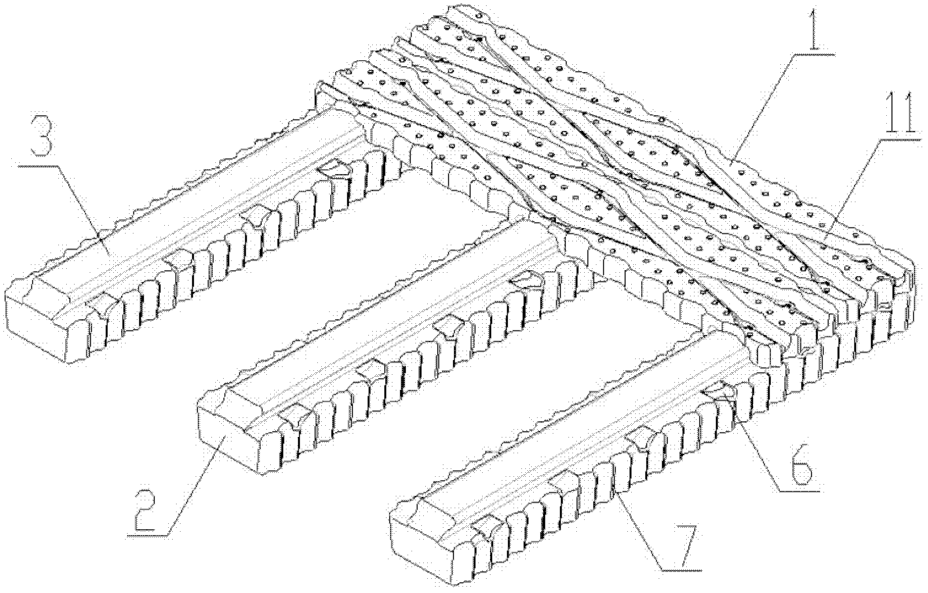
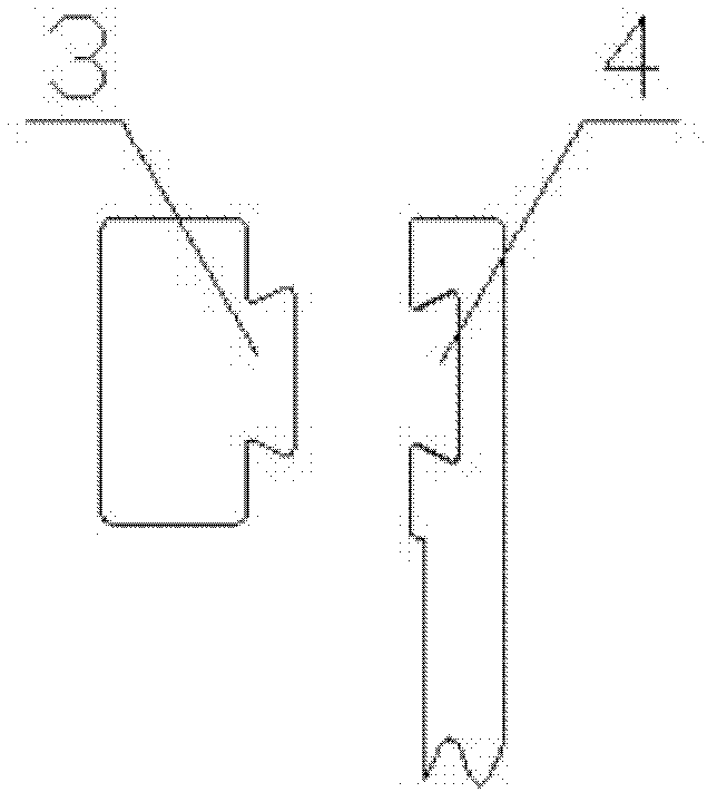
[0023] Such as Figures 1 to 8 As shown, the combined blow molding tray is composed of 6 panel units 1 and 3 legs 2. The panel unit 1 and the legs 2 are in a vertical position relationship with each other. The dovetail tenon 3 and the dovetail Slot 4 is used for plug-in combination. Protruding triangular slopes 5 are provided symmetrically on both sides of the dovetail groove 4 on the panel unit 1 , and concave triangular slopes 6 are provided at corresponding positions on both sides of the dovetail tenon 3 on the leg. The upper surface of the panel unit 1 is provided with intersecting grooves 11, and the surrounding facades of the panel unit 1 and the legs 2 adopt a wave-like structure 7, and the top angle of the wave is arc-shaped. An inwardly recessed elliptical ring reinforcing rib 8 is provided at the bottom of the panel unit 1 .

Embodiment 2

[0025] Such as Figure 9 , Figure 10 Another embodiment of the combined blow molded tray is given. The combined blow molding tray is composed of 6 panel units 1 and 3 legs 2. The relationship between the panel unit 1 and the legs 2 is perpendicular to each other. Dock combination. Protruding hemispherical row structures 9 are arranged symmetrically on both sides of the dovetail groove 4 on the panel unit 1 , and recessed hemispherical structures 10 are arranged on corresponding positions on both sides of the dovetail tenon 3 on the leg. The upper surface of the panel unit 1 is provided with intersecting grooves 11, and the surrounding facades of the panel unit 1 and the legs 2 adopt a wave-like structure 7, and the top angle of the wave is arc-shaped. The bottom of the panel unit 1 is provided with an inwardly recessed diamond-shaped ring 12 reinforcing rib.


PUM


Abstract

The invention relates to a blow-molding tray, in particular to a combined blow-molding tray comprising a panel and supporting legs, wherein the panel is formed by combining panel units, the panel units are vertical to the supporting legs, the panel units are spliced and combined with the supporting legs through grooves in the panel units and corresponding raised structures on the supporting legs in a preferable way of a mortise and tenon structure, and a splicing and matching surface of the panel and the supporting legs is provided with a reverse backstop pin; and the upper surfaces of the panel units are provided with crossed grooves, the peripheral vertical faces of the panel units and the supporting legs are of wavy structures, vertex angles of waves are of circular arc shapes, and the bottoms of the panel units are provided with reinforcing ribs. Due to the adoption of the structure, the combined blow-molding tray can be freely dismounted and mounted, can be replaced after being damaged and has the advantages of high bearing capacity, long service life, low using cost, low cost of machining equipment and low energy consumption in manufacturing.

Description

technical field [0001] The invention relates to a blow molding tray, in particular to a combined blow molding tray. Background technique [0002] With the rapid development of the logistics industry, the demand for pallets is also increasing. Traditional pallets are made of wood, and a large amount of wood is needed to make wooden pallets. The felling of wood will destroy the ecological environment. Although the price of wooden pallets is low, they are often not high in strength. Once the load is too large and heavy, it will break and break, making it unusable; moisture resistance and fire resistance are poor, easy to mold and insects, and weak corrosion resistance; It is easy to have sharp burrs, iron nails, etc., which are easy to scratch and damage the goods; the assembly efficiency is low, and the wood reuse rate is low. [0003] Nowadays, because plastic pallets can overcome the above-mentioned shortcomings of wooden pallets, they are more and more widely used. Howeve...

Claims


Application Information

Patent Timeline
Patent Type & Authority Applications(China)
IPC IPC(8): B65D19/32B65D19/40B65D19/38
Inventor 张然
Owner 张然
Why Eureka
Try Eureka