Celled hybrid beam junction with composite connectors

A composite connection and hybrid beam technology, applied in bridges, bridge parts, bridge forms, etc., to achieve the effect of increasing the force transmission ratio, increasing the safety reserve, and improving the applicable span

Inactive Publication Date: 2012-07-11
CCCC HIGHWAY CONSULTANTS
View PDF5 Cites 22 Cited by
  • Summary
  • Abstract
  • Description
  • Claims
  • Application Information

AI Technical Summary

Problems solved by technology

[0009] The object of the present invention is to provide a composite beam joint with a cell with composite connectors, by arranging welding stud connectors on the steel cell top plate, bottom plate, and pressure plate and setting a perforated plate on the cell partition The connector transmits axial force and can bear the larger axial force of the main girder section of the hybrid girder cable-stayed bridge, which effectively solves the problem of the main beam of the long-span hybrid girder cable-stayed bridge and avoids a large number of welding stud connections in the steel grid room It has stronger operability and reliability, and improves the applicability of hybrid girder cable-stayed bridges

Method used


Image

  • Celled hybrid beam junction with composite connectors
  • Celled hybrid beam junction with composite connectors
  • Celled hybrid beam junction with composite connectors

Examples


Embodiment Construction

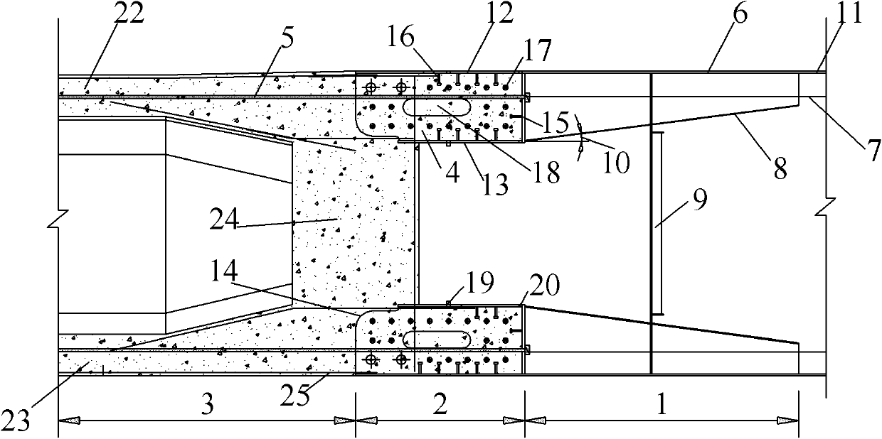
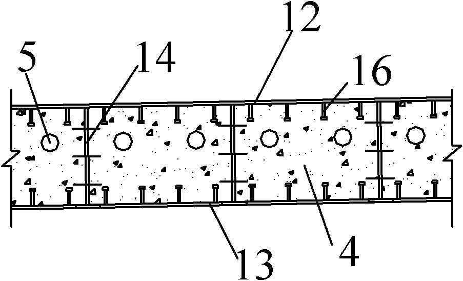
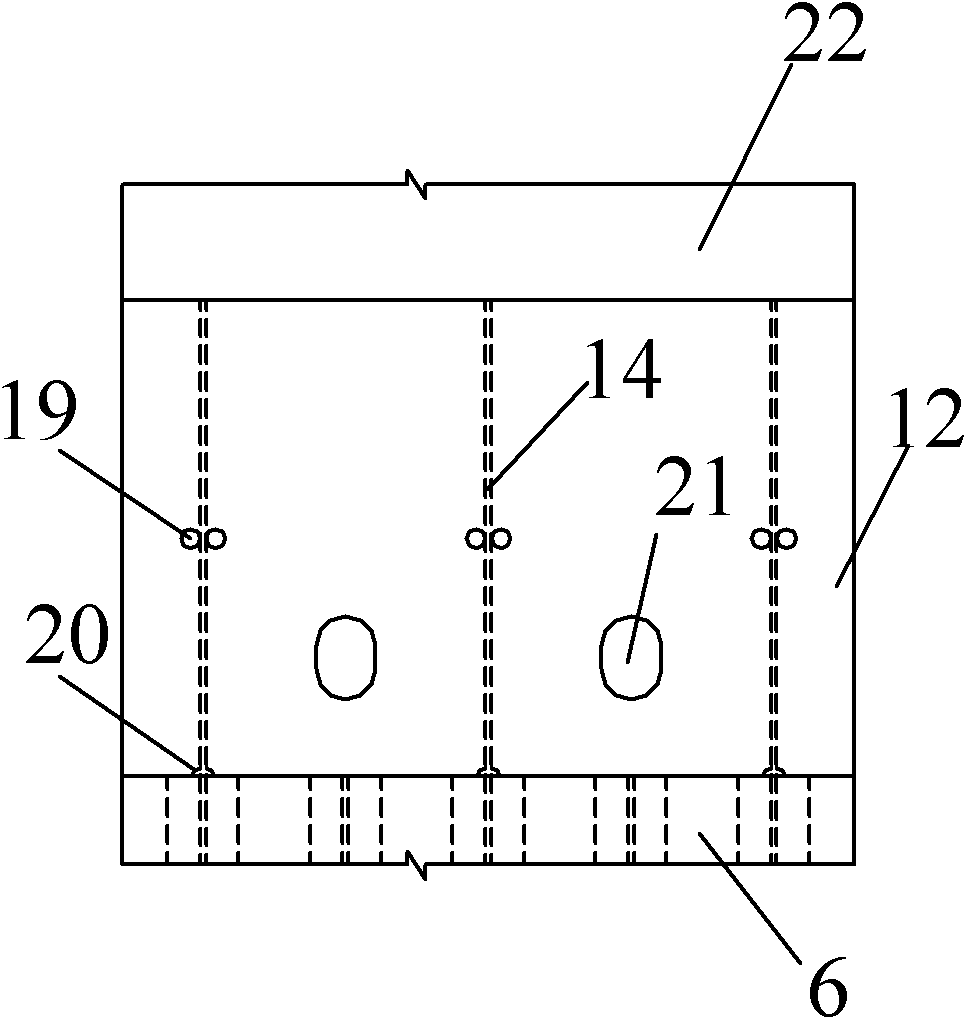
[0033] See figure 1 As shown in ~4, it is a hybrid beam joint with cells provided with composite connectors according to the present invention. It is composed of a steel beam transition section 1, a steel grid room 2 and a concrete beam transition section 3. The steel grid room 2 is filled with concrete 4 and is located between the steel beam transition section 1 and the concrete beam transition section 3. The longitudinal prestressed steel beams 5 pass through The steel cell 2 is placed on the pressure-bearing steel plate 15 . The steel beam transition section 1 is composed of a steel roof 6 , a U-shaped stiffener 7 , a variable-height stiffener 8 and a diaphragm 9 . The steel grid room 2 is connected to the steel main beam 11 through the steel beam transition section 1 . The steel roof 6 is at the same level as the steel girder 11, and is integrated by the horizontal extension of the steel girder 11, and extends horizontally to the top of the steel cell 2 to form the steel...


PUM


Abstract

The invention discloses a celled hybrid beam junction with composite connectors, which relates to the technique of bridge engineering and used for a main beam of a large-span hybrid beam cable-stayed bridge. Concrete-filled steel cell structures are disposed at the ends of a steel box girder, welding nail connectors are disposed on a top plate, a bottom plate and a bearing plate of each steel cell while the top plate, the bottom plate and the bearing plate are attached with concrete, and perforated plate connectors (PBL (perfobond leiste) connectors) are disposed on partition plates of each steel cell and integrally concreted with a concrete beam. When the celled hybrid beam junction is used, the main beam has the single-cell single-box, multi-cell and single box or single-cell and double-box cross section, and longitudinal prestress is applied to the interior of each steel cell. By means of the celled hybrid beam junction, the problem of stress of the main beam of the large-span hybrid beam cable-stayed bridge is solved effectively, structural safety is improved, welding of a great quantity of welding nail connectors in each steel cell is avoided, and the applicable span of the hybrid beam cable-stayed bridge is enlarged greatly.

Description

technical field [0001] The invention relates to the technical field of bridge engineering, in particular to a joint structure for the main girder of a long-span composite girder cable-stayed bridge. Background technique [0002] Hybrid girder cable-stayed bridge means that the main girder of the cable-stayed bridge is composed of two structural forms of concrete beam and steel beam along the length direction of the girder, and a joint structure is set between the concrete girder and the steel girder so that it can better bear the force together A form of cable-stayed bridge. [0003] The joint part of the main girder of the hybrid girder cable-stayed bridge is a structure that combines shear connectors, bearing plates, prestressed tendons, etc. to work together. Compared with steel box girder cable-stayed bridges or concrete girder cable-stayed bridges, hybrid girder cable-stayed bridges have been greatly improved in terms of mechanical performance, spanning capacity, and e...

Claims


Application Information

Patent Timeline
Patent Type & Authority Applications(China)
IPC IPC(8): E01D19/00E01D11/04
Inventor 徐国平刘高刘明虎吴文明
Owner CCCC HIGHWAY CONSULTANTS
Why Eureka
Try Eureka