Dry-soil-removed reinforced concrete screw pile forming device and method

A reinforced concrete screw and dry borrowing technology, which is applied to sheet pile walls, buildings, infrastructure engineering, etc., can solve the adverse effects of surrounding environment and pile quality, difficult to control the position and quality of steel bars, and cannot be applied to flat-bottomed screw piles. and other problems, to achieve the effect of easy control of engineering quality, improvement of pile quality, and improvement of bearing capacity value.

Active Publication Date: 2014-12-03
孔超
View PDF1 Cites 0 Cited by
  • Summary
  • Abstract
  • Description
  • Claims
  • Application Information

AI Technical Summary

Problems solved by technology

[0004] Yet the weak point of above-mentioned " screw pile, threaded pile forming equipment and pile forming method " is: it is only applicable to hillside foundation and gravel sand stratum, and can not be applicable to deep and thick soft soil stratum; Next is its steel bar placement method It is more difficult to control the position and quality of the steel bar after adopting the post-insertion; the third is that it is only suitable for tapered threaded piles, and cannot be used for flat-bottomed screw piles; the 200610019756. and Pile Construction Method" is a soil-squeezing pile, which has adverse effects on the surrounding environment and the quality of the pile.

Method used


Image

  • Dry-soil-removed reinforced concrete screw pile forming device and method
  • Dry-soil-removed reinforced concrete screw pile forming device and method
  • Dry-soil-removed reinforced concrete screw pile forming device and method

Examples


Embodiment Construction

[0026] The present invention will be further described in detail below in conjunction with the accompanying drawings and embodiments.

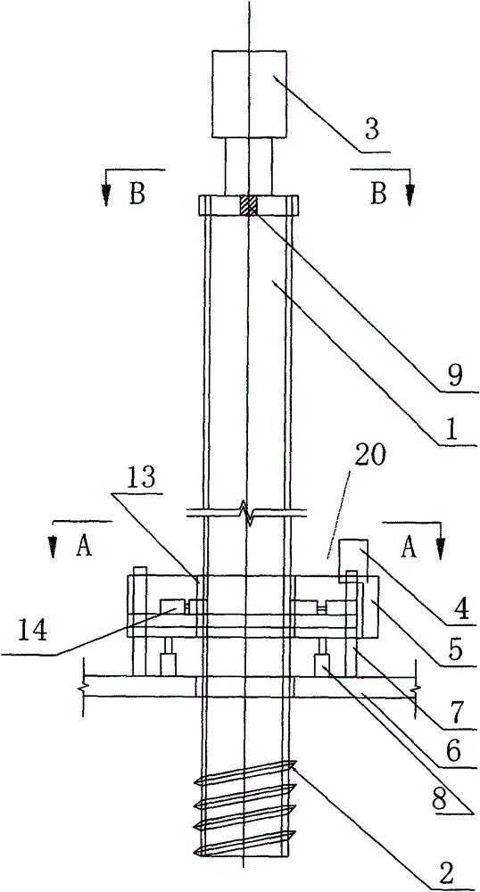
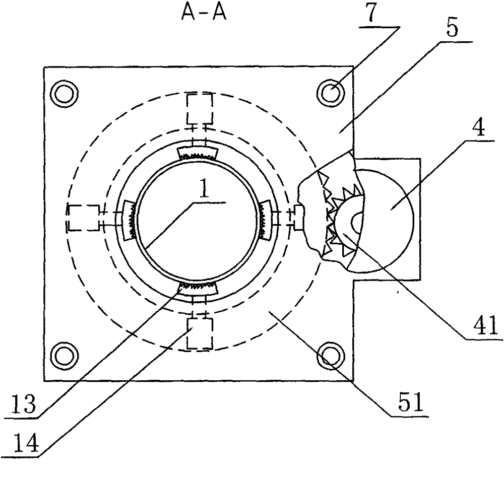
[0027] Figure 1 to Figure 4 An embodiment of the present invention is shown, which includes a steel mold tube 1 passing through the pile driver base 6, and a rotary power head 3 is arranged at the upper end of the steel mold tube.

[0028] The steel mold tube 1 is set as an opening at the bottom, and is welded with a threaded triangular steel bar 2 from the bottom of the tube to form a steel mold tube with an external helix. In order to ensure the pile reliability of the reinforced concrete screw pile, the external The number of turns of the spiral body must be greater than 3 turns;

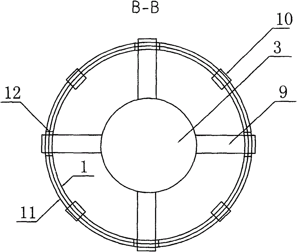
[0029] The top of the steel mold pipe 1 is provided with a rotary power head 3, and the bottom of the rotary power head 3 is connected with a cross-shaped connector 9, which can be welded with a cross-shaped steel bar, such as image 3 shown;

[0030] A steel...


PUM


Abstract

The invention provides a dry-soil-removed reinforced concrete screw pile forming device. The dry-soil-removed reinforced concrete screw pile forming device comprises a steel mould pipe, wherein the steel mould pipe penetrates through a base of a piling machine, and is provided with an external helicoid, a rotating power head is arranged at the upper end of the steel mould pipe, a cross-shaped connector is arranged at the lower part of the steel mould pipe, a steel hoop is welded to the top end of the steel mould pipe, a notch is formed at one end of the steel hoop, and is matched with the cross-shaped connector, clamps are arranged between the steel hoop and a base of the rotating power head, and can be connected with each other to form a whole, and an auxiliary rotating power device is arranged at the middle part of the steel mould pipe. A pile forming method comprises the following steps of: firstly, arranging the steel mould pipe in place, starting the power head to screw the steel mould pipe into a soil layer, starting the auxiliary rotating power device to a designed elevation in the case that the steel mould pipe enters a hard soil layer, completely removing soil in the steel mould pipe, putting a reinforcing cage into the steel mould pipe, grouting and filling concrete into the steel mould pipe, and inversely rotating the power head to check height of the concrete in the steel mould pipe so as to ensure dimension of the external helicoids of the pile until the steel mould pipe gets away from the soil layer, so that a screw pile is formed. The dry-soil-removed reinforced concrete screw pile forming device and the pile forming method provided by the invention have the advantages of high bearing capacity, high pile forming quality, environment friendliness and energy-saving performance, and is particularly applicable to a deep soft soil layer and a flat-bottomed screw pile.

Description

technical field [0001] The invention relates to a pile foundation of civil construction engineering, in particular to a pile-forming device and a pile-forming method of a dry-extracted reinforced concrete screw pile used for supporting a superstructure in a deep saturated soft clay stratum. Background technique [0002] Such as the invention patent of Chinese patent application number 200610019756.6 "screw pile, screw pile pile forming equipment and pile forming method", the structure of the pile forming equipment is mainly composed of body, oil cylinder, hydraulic motor, automatic control equipment, transmission pipeline, a power head Installed on the base frame of the body, the hydraulic motor is installed on the base of the body, the hydraulic motor is connected with the power head through a telescopic oil cylinder, the jig on the drill pipe is connected with the movable clamp of the power head The concrete conveying pipe is connected with the inner drill pipe, and the au...

Claims


Application Information

Patent Timeline
Patent Type & Authority Patents(China)
IPC IPC(8): E02D5/66E02D7/22E02D5/38E02D5/56
Inventor 孔超
Owner 孔超
Why Eureka
Try Eureka