Plugging method for downcomer for well-point dewatering of deep foundation pit

A technology of well point dewatering and dewatering pipe, applied in infrastructure engineering, construction and other directions, can solve problems such as difficult construction, difficulty in plugging, and many hidden dangers, and achieve the effects of reducing construction costs, improving construction quality, and fast construction progress.

Active Publication Date: 2012-07-11
CHINA MCC17 GRP
View PDF6 Cites 19 Cited by
  • Summary
  • Abstract
  • Description
  • Claims
  • Application Information

AI Technical Summary

Problems solved by technology

[0002] During the construction of high-rise buildings, due to the high groundwater level and the deep excavation of the foundation pit, it is generally necessary to use the well point dewatering method for dewatering, so as to facilitate the excavation of the foundation pit and the construction of the foundation. However, after the foundation construction is completed and the well point is removed For dewatering equipment, due to the effect of groundwater pressure, it will be difficult to block the downwater pipe. Generally, gravel is filled in the downwater pipe, and then

Method used


Image

  • Plugging method for downcomer for well-point dewatering of deep foundation pit
  • Plugging method for downcomer for well-point dewatering of deep foundation pit

Examples


Embodiment

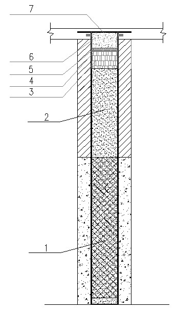
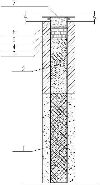
[0026] In the 8# building of the Lianhua Village Group B project in Nanjing, the downwater pipe plugging method of the deep foundation pit well point precipitation is adopted. The construction steps are: retain the filter layer 1 buried during the drainage and precipitation construction, fill the sand layer 2, medium and fine Fill it with sand to a depth of 1.5m downward from the top of the downcomer, and then seal it with a 0.8m thick cotton wool layer 3, followed by a 50mm thick water glass cement slurry layer 4 (sealed and set) and a 50mm thick The plugging king layer 5, the upper part of the plugging king layer 5 is poured to the upper end of the downcomer with a C35 micro-expansion concrete layer 6, and finally the downcomer is fully welded on the micro-expansion cement layer 6 with a 10mm thick round steel plate 7 Concrete was poured on the top of the round steel plate 7, and the concrete floor was poured flush with 40mm thick fine stone concrete. After repeated inspectio...


PUM

PropertyMeasurementUnit
Granularityaaaaaaaaaa

Abstract

The invention provides a plugging method for a downcomer for the well-point dewatering of a deep foundation pit, and belongs to a falling water plugging method of civil engineering. The plugging method comprises the construction steps as follows: firstly, a filtering layer is disposed; secondly, a sand layer is filled; thirdly, a cotton batting layer is stuffed; fourthly, a soluble glass cement sand bed is poured; fifthly, a leaking stoppage agent layer is smeared; sixthly, a micro-expansive concrete layer is poured; and seventhly, a plugging steel plate is welded, wherein the filtering layer arranged at the lower part of an inner chamber of a conventional downcomer remains the same, and the sand layer is filled until the height of the sand layer reaches 1.5 meters below the top of the downcomer; the height of the cotton batting layer ranges from 0.7 to 1.0 m; the thickness of the soluble glass cement sand bed ranges from 50 to 80 mm, and the soluble glass cement sand bed is curdled when poured; the thickness of the leaking stoppage agent layer ranges from 40 to 60 mm; the micro-expansive concrete layer is poured until the height reaches the upper pipe orifice of the downcomer; and the round steel plate is utilized to plug an upper opening of the downcomer above the micro-expansive concrete layer in a full-length welding manner, wherein the thickness of the round steel plate ranges from 8 to 15 mm. The plugging method effectively solves the difficult problem that leakage is caused when the downcomer is plugged, is simple and convenient to operate, and has the advantages of quick construction progress, high construction quality and low cost.

Description

technical field [0001] The invention belongs to a plugging method for dewatering in industrial and civil construction, in particular to a plugging method for dewatering at well points of deep foundation pits. Background technique [0002] During the construction of high-rise buildings, due to the high groundwater level and the deep excavation of the foundation pit, it is generally necessary to use the well point dewatering method for dewatering in order to facilitate the excavation of the foundation pit and the construction of the foundation. However, after the foundation construction is completed and the well point is removed For dewatering equipment, due to the effect of groundwater pressure, it will be difficult to block the downwater pipe. Generally, gravel is filled in the downwater pipe, and then high-grade concrete is poured until the concrete roof is below 50mm, and then a 10mm thick steel plate is used to seal the downwater. The pipe is welded and sealed, but due to...

Claims


Application Information

Patent Timeline
IPC IPC(8): E02D19/10E02D19/20
Inventor 刘宝堂
Owner CHINA MCC17 GRP
Why Eureka
Try Eureka