Supercharge Your Innovation With Domain-Expert AI Agents!

Sunlight plate connection component applied to roof sunlight plate system

A technology for connecting components and sunshine boards, which is applied in the field of sunshine rooms, can solve problems such as inability to eliminate, waste, increase construction costs, etc., and achieve the effect of saving installation time

Active Publication Date: 2012-07-11
SHANGHAI HUILI TUVGAL SHEETAB
View PDF9 Cites 2 Cited by
  • Summary
  • Abstract
  • Description
  • Claims
  • Application Information

AI Technical Summary

Problems solved by technology

[0002] At present, in the roof solar panel system, the PC board and the lower steel structure are fixed by screws. However, due to the relatively large thermal expansion and contraction of the solar panel (0.065mm / m.℃), the traditional installation of the solar panel In the method, it is strictly forbidden to fix parts such as self-tapping screws directly through the sun board and the lower steel structure, in case the temperature changes cannot eliminate the influence caused by the size extension or shortening of the sun board, which will cause the surface of the sun board to bulge and affect the appearance. , There is a gap between the rubber strip and the surface of the sun board, which causes leakage, and the internal stress of the sun board is too large, which causes cracks at the self-tapping nails, etc.
In order to avoid stress cracking caused by thermal expansion and cold contraction of the solar panel, it is necessary to drill enlarged holes in advance when fixing with cap nails. This method of fixing without self-tapping screws through the solar panel greatly reduces the resistance of the solar panel to resist negative wind pressure. Ability to reduce the installation size of the sun panel, increase the joints of the sun panel, and increase the thickness of the sun panel, which not only increases the probability of leakage, but also is very troublesome to install, increases the construction cost, and causes unnecessary waste

Method used


Image

  • Sunlight plate connection component applied to roof sunlight plate system
  • Sunlight plate connection component applied to roof sunlight plate system

Examples


Embodiment Construction

[0015] In order to make the technical means, creative features, goals and effects achieved by the present invention easy to understand, the present invention will be further described below in conjunction with specific embodiments.

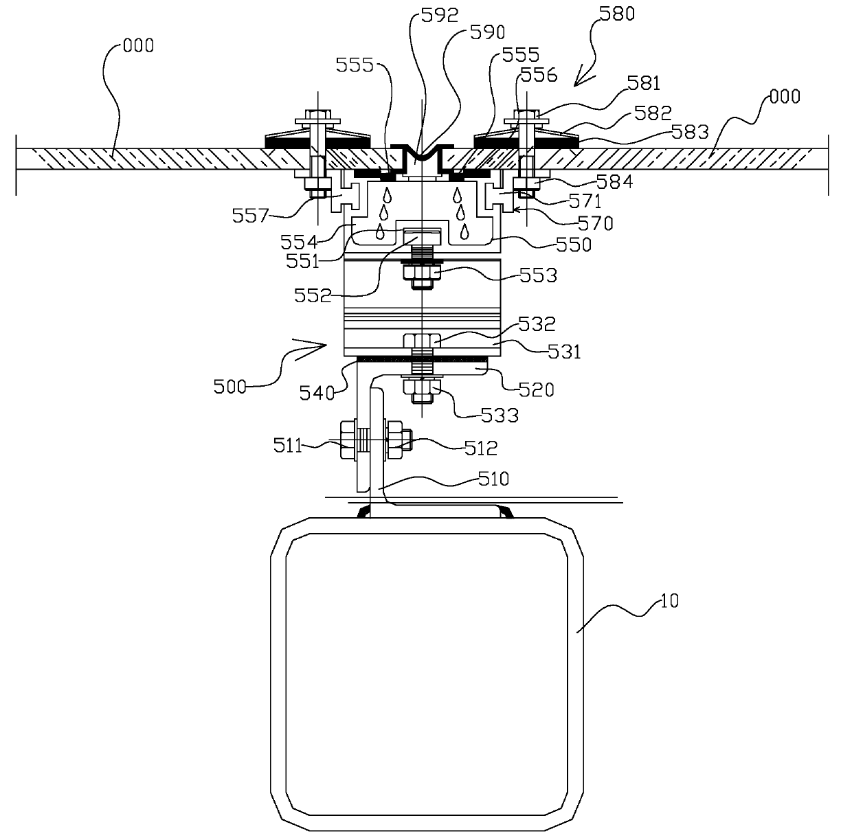
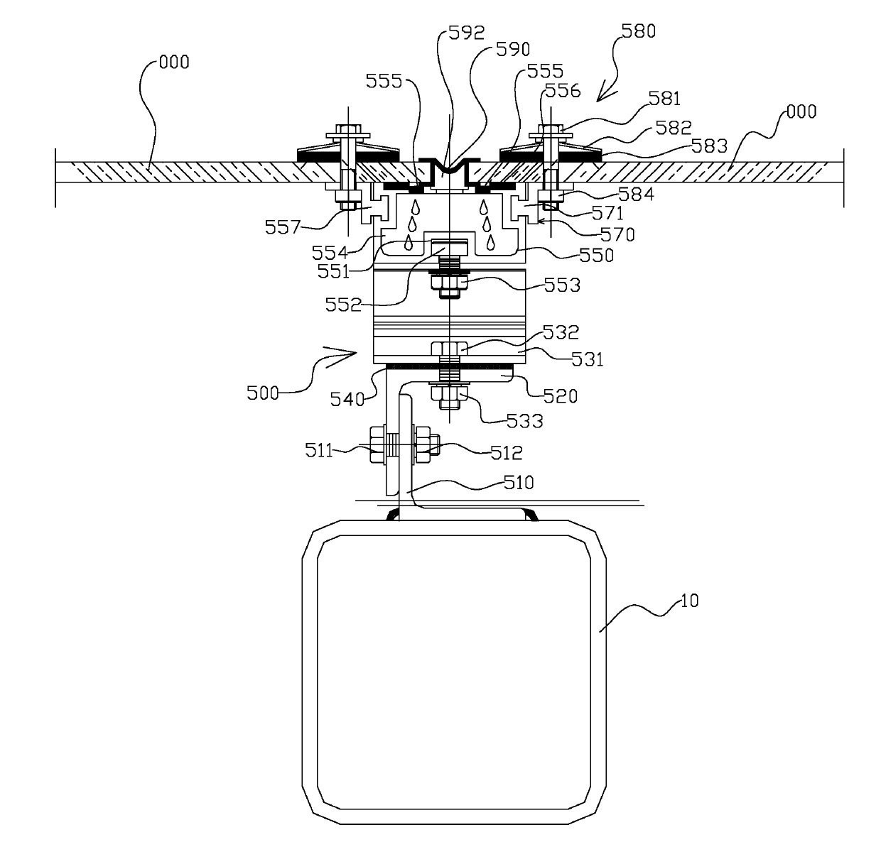
[0016] see figure 1 , the solar panel connection member 500 shown in the figure comprises the lower angle steel 510 welded on the square steel pipe purlin 10 in the support structure and the upper angle steel 520 fixed on the lower angle steel 510 by bolts 511 and nuts 512, the upper and lower angle steels 520, 510 forms an angle steel support.

[0017] The underboard sliding bearing 530 is a profile, and the bottom surface of the underboard sliding bearing 530 is provided with an underboard sliding groove 531 extending along the underboard sliding bearing 530. The length of the underboard sliding groove 531 is the same as that of the board The lower slide supports 530 are equal in length. Insert the head of the bolt 532 into the sliding groove ...


PUM


Abstract

The invention discloses a sunlight plate connection component applied to a roof sunlight plate system. The sunlight plate connection component comprises an angle steel support, a plate down-sliding support, a plate up-sliding support, two plate sliding support lugs and multiple plate point type connection components, wherein the angle steel support is fixed on a square steel pipe purline in a support framework; the plate down-sliding support is mounted on the angle steel support in a sliding manner through a bolt and a nut; the plate up-sliding support is fixedly mounted on the plate down-sliding support through a bolt and a nut; the two plate sliding support lugs are arranged on the side surface of the plate up-sliding support in a sliding manner; and the plate point type connection components connect the sunlight plate with the plate sliding support lugs. In the invention, a pulling rivet can directly pass through the sunlight plate without drilling an expansion hole on the sunlight plate in advance, thus the mounting time is saved; and the sunlight plate connection component can automatically release the inner stress generated by the heat expansion and cold contraction of the sunlight plate so as to eliminate the surface upheaval of the sunlight plate caused by excessive inner stress of the sunlight plate and the leakage caused by the gap between an adhesive tape and the surface of the sunlight plate.

Description

technical field [0001] The invention relates to the technical field of sunshine rooms, in particular to a sun panel connecting member applied to a roof sun panel system. Background technique [0002] At present, in the roof solar panel system, the PC board and the lower steel structure are fixed by screws. However, due to the relatively large thermal expansion and contraction of the solar panel (0.065mm / m.℃), the traditional installation of the solar panel In the method, it is strictly forbidden to fix parts such as self-tapping screws directly through the sun panel and the lower steel structure, in case the temperature changes cannot eliminate the influence caused by the size extension or shortening of the sun panel, which will cause the surface of the sun panel to bulge and affect the appearance. 1. There is a gap between the rubber strip and the surface of the sun board, which causes leakage, and the internal stress of the sun board is too large, which causes cracks at th...

Claims


Application Information

Patent Timeline
Patent Type & Authority Applications(China)
IPC IPC(8): E04D3/36E04D12/00E04D13/04
Inventor 沈晓茳
Owner SHANGHAI HUILI TUVGAL SHEETAB
Features
  • R&D
  • Intellectual Property
  • Life Sciences
  • Materials
  • Tech Scout
  • Unparalleled Data Quality
  • Higher Quality Content
  • 60% Fewer Hallucinations
Learn More