Manifold system for sand blender

A technology of manifold system and sand mixing equipment, which is applied in the direction of mining fluid, wellbore/well components, earthwork drilling and production, etc., can solve the problems of single operation mode and inconvenient construction layout, so as to improve work efficiency and highlight substantive features , the effect of improving flexibility

Inactive Publication Date: 2012-07-11
YANTAI JEREH PETROLEUM EQUIP & TECH
View PDF6 Cites 90 Cited by
  • Summary
  • Abstract
  • Description
  • Claims
  • Application Information

AI Technical Summary

Problems solved by technology

[0003] The purpose of the present invention is to overcome the above-mentioned deficiencies in the prior art, and provide a manifold system for sand mixing equipment, which mainly solves the prob

Method used


Image

  • Manifold system for sand blender
  • Manifold system for sand blender
  • Manifold system for sand blender

Examples


Embodiment 1

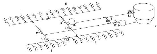
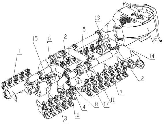
[0014] Example 1, see figure 1 , 2 , processed into a suction header welding assembly and a discharge header welding assembly, install the first butterfly valve 1, the fifth butterfly valve 5, and the ninth butterfly valve with pneumatic head devices on the connecting flange of the suction header welding assembly 9, wherein the fifth butterfly valve 5 and the first butterfly valve 1 need to be N according to the design, N is greater than or equal to 1, and N is a positive integer, and the third butterfly valve with a pneumatic head device is installed on the connecting flange of the discharge header welding assembly. Butterfly valve 3, seventh butterfly valve 7 and tenth butterfly valve 10, wherein the number of seventh butterfly valve 7 and third butterfly valve 3 is N according to the design requirements, N is greater than or equal to 1, and N is a positive integer, and the ninth butterfly valve 9 and the tenth butterfly valve 10 are respectively Located on the connecting f...


PUM


Abstract

The invention discloses a manifold system for a sand blender, which comprises a suction header welding assembly, a discharge header welding assembly, a suction manifold, a discharge manifold, a suction centrifugal pump (15), a discharge centrifugal pump (14), butterfly valves and a sand blending tank (16). Two ends of the suction centrifugal pump (15) are connected with the suction header welding assembly and the suction manifold, the suction manifold is connected with the sand blending tank (16), two ends of the discharge centrifugal pump (14) are connected with the sand blending tank (16) and the discharge manifold, and electromagnetic flow meters (17) are respectively disposed on outer circle surfaces of the suction manifold and the discharge manifold. The manifold system is characterized in that the sixth butterfly valve (6) with a pneumatic head device and the thirteenth butterfly valve (13) with a pneumatic head device are disposed on the suction manifold, the twelfth butterfly valve (12) with a pneumatic head device and the fourth butterfly valve (4) with a pneumatic head device are disposed on the discharge manifold, and the butterfly valves (1, 5, 9, 3, 7 and 10) with pneumatic head devices are arranged on the suction header welding assembly and the discharge header welding assembly. A double-suction and double-discharge operation mode can be realized, flexibility of field operation is improved, and the manifold system brings great convenience for field layout and construction.

Description

technical field [0001] The invention relates to the technical field of sand mixing equipment, in particular to a manifold system for sand mixing equipment, which is mainly used for oil field sand mixing equipment. Background technique [0002] At present, the function of the sand mixing equipment is to fully mix the fracturing fluid suction and the proppant in the sand mixing tank through the suction manifold system in a certain proportion, and deliver the mixed sand glue liquid to the fracturing equipment through the discharge manifold system. It is pumped by the fracturing equipment to the bottom of the well for fracturing. At the oil field site, several fracturing equipment, one sand mixing equipment, one instrument equipment and one liquid supply equipment are required to work together to complete the fracturing operation. Due to the different site conditions of different oil fields, the site space is very limited, and the number of operating equipment is large, which b...

Claims


Application Information

Patent Timeline
IPC IPC(8): E21B43/26
Inventor 赵鲁海吴义朋杨雅静
Owner YANTAI JEREH PETROLEUM EQUIP & TECH
Why Eureka
Try Eureka