Easily controlling hydraulic corner self-servo valve

A technology of self-servo and rotation angle, applied in the field of servo valve, can solve the problems of unsatisfactory dynamic characteristics of the valve core, unbalanced radial force of the valve core, easy formation of dead space of the valve core, etc., and achieve small deformation of the valve port, resistance and Small hydraulic clamping force and good dynamic characteristics

Active Publication Date: 2012-07-11
武汉科技大学资产经营有限公司
View PDF4 Cites 27 Cited by
  • Summary
  • Abstract
  • Description
  • Claims
  • Application Information

AI Technical Summary

Problems solved by technology

The radial force of the spool of the servo valve is balanced, and the resistance of the spool is reduced, but at the same time, there is also the problem that one end of the spool is easy to form a dead space. The spool generates a large axial force, the dynamic characteristics of the spool are not very ideal, and the servo dead zone has been improved but not ideal; It brings difficulties such as difficult preparation and processing of dark oil passages inside the valve body

Method used


Image

  • Easily controlling hydraulic corner self-servo valve
  • Easily controlling hydraulic corner self-servo valve
  • Easily controlling hydraulic corner self-servo valve

Examples


Embodiment 1

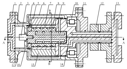
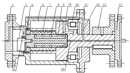
[0039] An easy-to-control hydraulic angle self-servo valve, such as figure 1 and figure 2 As shown, the hydraulic rotary self-servo valve includes a fixed block 5 , a cylinder body 6 , a valve body 7 , a valve sleeve 8 , a valve core 9 and vanes 15 .

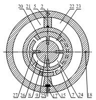
[0040] The left end cover 1 is installed on the left end of the cylinder body 6, and the cylinder body 6 close to the left end is provided with a dividing plate 16, and the inner wall of the upper part of the cylinder body 6 on the right side of the dividing plate 16 is equipped with a fixed stopper 5, and the fixed stopper 5 is connected with the valve. The body 7 is a dynamic fit, and a stopper sealing strip is installed between the fixed stopper 5 and the valve body 7; the outer wall of the hollow cylinder 35 of the valve body 7 is fixedly equipped with a blade 15, and the blade 15 is a dynamic fit with the cylinder body 6. A blade sealing strip 25 is installed between the blade 15 and the cylinder body 6; the initial assem...

Embodiment 2

[0054] An easy-to-control hydraulic angle self-servo valve. Except following technical parameter, all the other are with embodiment 1.

[0055] There are 2 valve ports evenly opened on the 4 prime lines of the cylindrical surface of the valve core 9, and the valve ports on each prime line communicate through oil passages, the 4 prime lines are evenly distributed, and the 2 valve ports on each prime line The port is located in the same cross-section as the valve ports corresponding to the other prime lines;

[0056] The cylindrical surface of the valve sleeve 8 is evenly provided with two upper semicircular oil ring grooves 36 and two lower semicircular oil ring grooves 37 along the axis.

Embodiment 3

[0058] An easy-to-control hydraulic angle self-servo valve. Except following technical parameter, all the other are with embodiment 1.

[0059] There are 4 to 5 valve ports evenly opened on the 4 plain lines of the cylindrical surface of the valve core 9, and the valve ports on each plain line are communicated through oil passages, and the 4 plain lines are evenly distributed, and 4 valve ports on each plain line ~5 valve ports are located in the same cross-section as the valve ports corresponding to the rest of the prime lines;

[0060] The cylindrical surface of the valve sleeve 8 is evenly provided with 4 to 5 upper semicircular oil ring grooves 36 and 4 to 5 lower semicircular oil ring grooves 37 along the axis.

[0061]

[0062] The high-pressure oil inlet P of this specific embodiment enters the high-pressure oil passage 2 of the cylinder 6 through its oil passage, enters the high-pressure outer oil ring groove 31 of the valve body 7 through the outlet of the high-pres...


PUM


Abstract

The invention relates to an easily controlling hydraulic corner self-servo valve which is characterized in that a blade (15) is arranged on the outer wall of a hollow column body (35) of a valve body (7); the initial assembly position of the blade (15) is in axis symmetric arrangement with that of a fixed baffle block (5); a valve sleeve (8) is arranged in a the hollow column body (35), and a valve core (8) is arranged in a small hollow circle (34) of the valve body (7); a high pressure oil inlet P and a low pressure oil outlet T of a left end cover (1) are respectively communicated with high and low pressure outer oil annular slots (31 and 28) of the valve body (7) correspondingly through high and low pressure oil channels (2 and 17) of a cylinder body (6); high and low pressure inner oil annular slots (32 and 30) of the valve body (7) are correspondingly communicated with core body high and low pressure oil annular slots (39 and 40) of the valve core (9); and core body high and low pressure oil channels (38 and 41) enter a first working chamber and a and second working chamber correspondingly through upper and lower semi-circle oil annular slots (36 and 37) of the valve sleeve (8). According to the invention, the easily controlling hydraulic corner self-servo valve has the characteristics that the preparation is convenient, the radial force and the axial force subjected by the valve core are both balanced, the resistance of the valve core is low, the dynamic characteristics are good, and the servo blind area is small.

Description

technical field [0001] The invention belongs to the technical field of servo valves, in particular to an easy-to-control hydraulic angle self-servo valve. Background technique [0002] The hydraulic angle self-servo valve is the core component of the hydraulic control system. It is widely used in industry. It can convert the small power input by the motor into the high power output by the hydraulic pressure, so as to control the precise rotation angle of the equipment with large torque. [0003] At present, the hydraulic servo joint researched by domestic scholars such as Yangzhou University Zhu Xinglong first used the hydraulic angle servo concept (Zhu Xinglong, Yan Jingping, Zhou Jiping, Miao Handong, Shan Yicai. Degree of freedom hydraulic servo joint dynamics modeling and simulation research. Mechanical design and Manufacturing Engineering, 2002,31(6):23-25.), (Zhu Xinglong, Zhou Jiping. Stability of a hydraulic servo joint and its steady-state error analysis. Control En...

Claims


Application Information

Patent Timeline
IPC IPC(8): F15B13/02
Inventor 蒋林陈新元向贤宝赵杰曾良才赵慧金晓宏侯宇曾镛雷斌刘白雁许仁波
Owner 武汉科技大学资产经营有限公司
Why Eureka
Try Eureka