Compact buffering cylinder

A buffer cylinder, a compact technology, applied in the field of buffer cylinders, can solve the problems of large bore diameter and large floor space of the buffer cylinder, and achieve the effect of increasing the force-bearing area of ​​the buffer, good buffering effect, and reducing the bore diameter

Active Publication Date: 2012-07-11
江苏朗能机械科技有限公司
View PDF6 Cites 2 Cited by
  • Summary
  • Abstract
  • Description
  • Claims
  • Application Information

AI Technical Summary

Problems solved by technology

The disadvantage of this structure is that the end face of the piston rod bears the force during buffering. In order to ensure the buffering effect, the bore diameter of the buffering cylinder is required to be large, and the floor space is large. The number and arrangement of the buffering cylinders are limited to a certain extent.

Method used


Image

  • Compact buffering cylinder
  • Compact buffering cylinder

Examples


Embodiment Construction

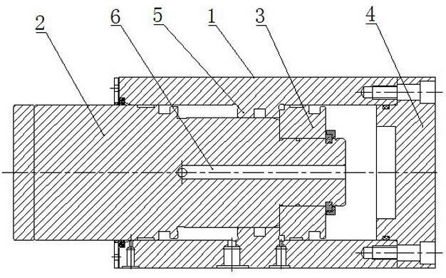
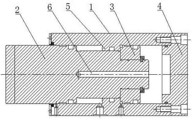
[0007] Such as figure 1 As shown, it includes a cylinder body 1, a piston rod 2, a piston 3, an end cover 4, an isolation ring 5, and a guide channel 6.

[0008] A protruding spacer ring 5 is provided in the middle part of the inner wall of the cylinder body 1, and an end cover 4 is provided at the lower end of the cylinder body 1. The piston rod 2, the spacer ring 5 and the upper part of the cylinder body 1 cooperate to form an upper cylinder structure. , Cooperate with the lower part of the cylinder body 1 to form a lower oil cylinder structure.

[0009] The specific structure is: the piston rod 2 is a stepped cylinder with three sections of cylinders, and the diameters of the stepped cylinders decrease successively. The lower cylinder of piston rod 2 stretches into the lower cavity of cylinder body 1 and is connected and fixed with piston 3, the middle cylinder of piston rod 2 is slidingly fitted with spacer ring, and the upper end cylinder of piston rod 2 is slidingly fit...


PUM


Abstract

The invention relates to a compact buffering cylinder which comprises a cylinder body and a piston rod. The compact buffering cylinder is characterized in that the middle part of the inner wall of the cylinder wall is provided with a raised isolating ring, the isolating ring, the piston rod and the upper part of the cylinder body match one another to form an upper oil cylinder structure, the isolating ring, the piston rod and the lower part of the cylinder body match one another to form a lower oil cylinder structure, a diversion channel is drilled on the piston rod, and the upper port and the lower port of the diversion channel are communicated with the upper cavity of the upper oil cylinder structure and the lower cavity of the lower oil cylinder structure respectively. During buffering, the upper cavity and the lower cavity are both filled with hydraulic oil and matched with all valve groups of a hydraulic system to bear impact and finish buffering, thus the buffering force carrying area of the buffering cylinder is increased, the diameter is decreased, and the volume and the manufacturing cost are reduced. In addition, because the buffering cylinder is small in volume, the buffering cylinder can be arranged on multiple points to achieve multi-point buffering with good effect.

Description

technical field [0001] The invention relates to a buffer cylinder, in particular to a compact buffer cylinder with small volume and good buffer effect. Background technique [0002] The buffer hydraulic cylinder is a hydraulic cylinder with buffer function, which is widely used in mechanical fields such as excavators or blanking hydraulic machines. The traditional hydraulic press buffer device includes a buffer cylinder installed on the workbench and an upper limit set on the side wall of the slider. When the slider slows down, the rodless cavity of the buffer cylinder is filled with oil to achieve buffering of the corresponding tonnage. The disadvantage of this structure is that the end face of the piston rod bears the force during buffering. In order to ensure the buffering effect, the bore of the buffering cylinder is required to be large and occupy a large area. The number and arrangement of the buffering cylinders are subject to certain limitations. Contents of the in...

Claims


Application Information

Patent Timeline
Patent Type & Authority Applications(China)
IPC IPC(8): F15B15/14F15B15/22
Inventor 黄城镇袁志刚施海峰
Owner 江苏朗能机械科技有限公司
Why Eureka
Try Eureka