Kenter shackle

a kenter shackle and shackle technology, applied in the direction of shackles, hauling chains, chain elements, etc., can solve the problems of high notch stress in the transition, inability to strengthen the weakened areas, and the half-chain elements are undamaged

Active Publication Date: 2021-02-16
SCHMIEDESTUECK VERTRIEB FEUERSTEIN
View PDF6 Cites 0 Cited by
  • Summary
  • Abstract
  • Description
  • Claims
  • Application Information

AI Technical Summary

Benefits of technology

[0007]The empty space is provided in the half element above the toothing at the top in the direction of the load, which is designed either as a groove running around above the toothing or as a pocket recessed over the entire surface. The outer circumference of the groove or pocket is also rounded with a large radius. In this way, the tensile stresses are held longer in the outer circumferential area of the leg or transferred around the toothing receptacle to the adjoining arc area on the half element.
[0010]As soon as the half elements are connected, a so-called coupling piece is inserted between them. It divides the oval formed by the half elements inserted into each other into an eight and also prevents the half elements pushed into each other laterally from drifting apart again. It also braces the half elements against each other when the Kenter shackle is under load, reducing deformation in the oval.
[0012]In a preferred embodiment, a specially designed coupling piece is provided, which can be fastened without the long notched pin, so that, in particular, the bores in the half elements are significantly reduced in length and no longer extend into the outer zones next to the toothing receptacle, which have to absorb all tensile stresses. The points of weakness in the half elements, which are formed by the bore in conventional fastening, are thus eliminated in this preferred embodiment.
[0013]The improved coupling piece provides two bolts in one transverse bore, which can be pushed outwards via a central spreader element. In this way, the ends of the bolts, which are in particular hemispherically rounded or also conically or cylindrically shaped, protrude from the base body of the coupling element and can engage in corresponding receptacles on the inner flanks of the half elements. Lateral stop surfaces, which interact with corresponding protrusions or recesses on the inner flanks of the half elements, prevent the coupling piece from rotating around the bolt axis. Dismantling the Kenter shackle is much easier with this preferred embodiment, including under water using a diving robot. Only the hexagon socket screw on the coupling piece, which is preferably used as a spreader element, has to be loosened so that the two bolts can be pushed back in again. Due to the preferably spherical or conical shape of the ends of the bolts, they are automatically pushed back when the coupling piece is pulled out of the Kenter shackle. If this is not possible due to advanced corrosion, the coupling piece can be cut in the middle, leaving the half chain elements undamaged.

Problems solved by technology

The disadvantage of the well-known chain connector is that the toothing is relatively sharp-edged so that high notch stresses occur in the transitions between the planes and towards the remaining half element.
It is not possible to strengthen the weakened areas by simply increasing the wall thickness because the outer shape of the Kenter shackle must not be changed significantly since compatibility with the anchor chain links must be maintained.
If this is not possible due to advanced corrosion, the coupling piece can be cut in the middle, leaving the half chain elements undamaged.

Method used


Image

  • Kenter shackle
  • Kenter shackle
  • Kenter shackle

Examples


Embodiment Construction

[0019]The preferred embodiments of the present invention will now be described with reference to FIGS. 1-5 of the drawings. Identical elements in the various figures are designated with the same reference numerals.

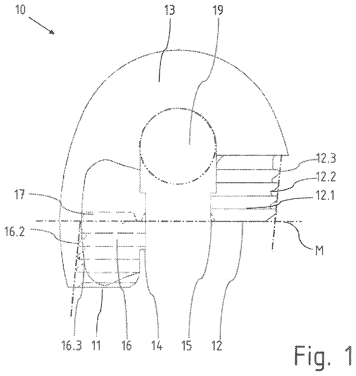
[0020]FIG. 1 shows a single half element 10 for a Kenter shackle in side view. The half element 10 essentially consists of a short leg 12 and a long leg 11, whereby the legs 11, 12 are connected to each other by a bent clasp 13.

[0021]As the side view in FIG. 1 further shows, the short leg 12 has an external toothing 12.1. An internal toothing 16.1 begins on the opposite long leg 11 at the level of the lower end of the short leg 12, which is formed in a hollow space 16 on the long leg 11. The transverse dashed-dotted line marks the center plane M and indicates the distinction between the cavity 16 with internal toothing 16.1 and a cavity 17 formed above the toothing area 16.1. Protrusions 14, 15 are visible on the sides of the legs 11, 12 pointing towards each other, whereb...


PUM


Abstract

The Invention relates to a Kenter shackle for anchor chains, at least comprising two half elements which can be coupled to one another and a coupling piece element that can be introduced between the half-elements wherein the half elements each have an L-shaped or J-shaped configuration, wherein the external toothing having a plurality of parallel toothing planes is formed at the end of a short connection leg and wherein a receiving chamber is formed at the end of a long connection leg, having an internal toothing with a plurality of parallel toothing planes, into which the external toothing of the short connection leg engages, and wherein the connection legs are connected to one another via a curved clasp. In addition, the receiving chamber in the long leg is extended by means of a cavity above the end side of the external toothing of the short leg and / or above the uppermost toothing plane of the internal toothing pointing towards the clasp.

Description

BACKGROUND OF THE INVENTION[0001]The invention relates to a Kenter shackle according to claim 1.[0002]With the chain link shown in DE 199 01 233 A1, the teeth of the half elements engage with each other such that only they are positively locked against tensile forces in the main load direction, but not transversely to it. The toothing is only effective one-dimensionally and not spatially. By aligning the center lines of the interlocking teeth obliquely to the center axis, the outer legs of the half elements can manage with only a relatively small reduction in wall thickness towards each end.[0003]A Kenter shackle, as known from the U.S. Pat. No. 8,087,227B2, for example, is a connector element consisting of at least two parts. It is used to subsequently connect two pieces of an anchor chain to each other and to be able to disconnect the connection again later, or to connect another part, in particular, the anchor itself, to an anchor chain. If the Kenter shackle is used as an anchor...

Claims


Application Information

Patent Timeline
Patent Type & Authority Patents(United States)
IPC IPC(8): F16G15/04F16G15/02F16G15/10F16G13/14
CPCF16G15/04F16G15/02F16G13/14F16G15/10
Inventor STUKENBERG, TILLSVERDLOVA, NINA
Owner SCHMIEDESTUECK VERTRIEB FEUERSTEIN
Why Eureka
Try Eureka