Spring Base Fixing Device For Vibration Damper

A technology of fixing device and spring seat, applied in the direction of shock absorber, spring, spring/shock absorber design characteristics, etc., can solve problems such as failure to meet safety requirements, traffic accidents, loss of car control, etc.

Inactive Publication Date: 2012-07-11
ZF FRIEDRICHSHAFEN AG
View PDF7 Cites 5 Cited by
  • Summary
  • Abstract
  • Description
  • Claims
  • Application Information

AI Technical Summary

Problems solved by technology

Through the changed spring force, the driving behavior of the vehicle is also changed, which may lead to a loss of control of the car and thus a traffic accident
In this view, the described structures may not meet the high safety requirements currently in force

Method used


Image

  • Spring Base Fixing Device For Vibration Damper
  • Spring Base Fixing Device For Vibration Damper
  • Spring Base Fixing Device For Vibration Damper

Examples


Embodiment Construction

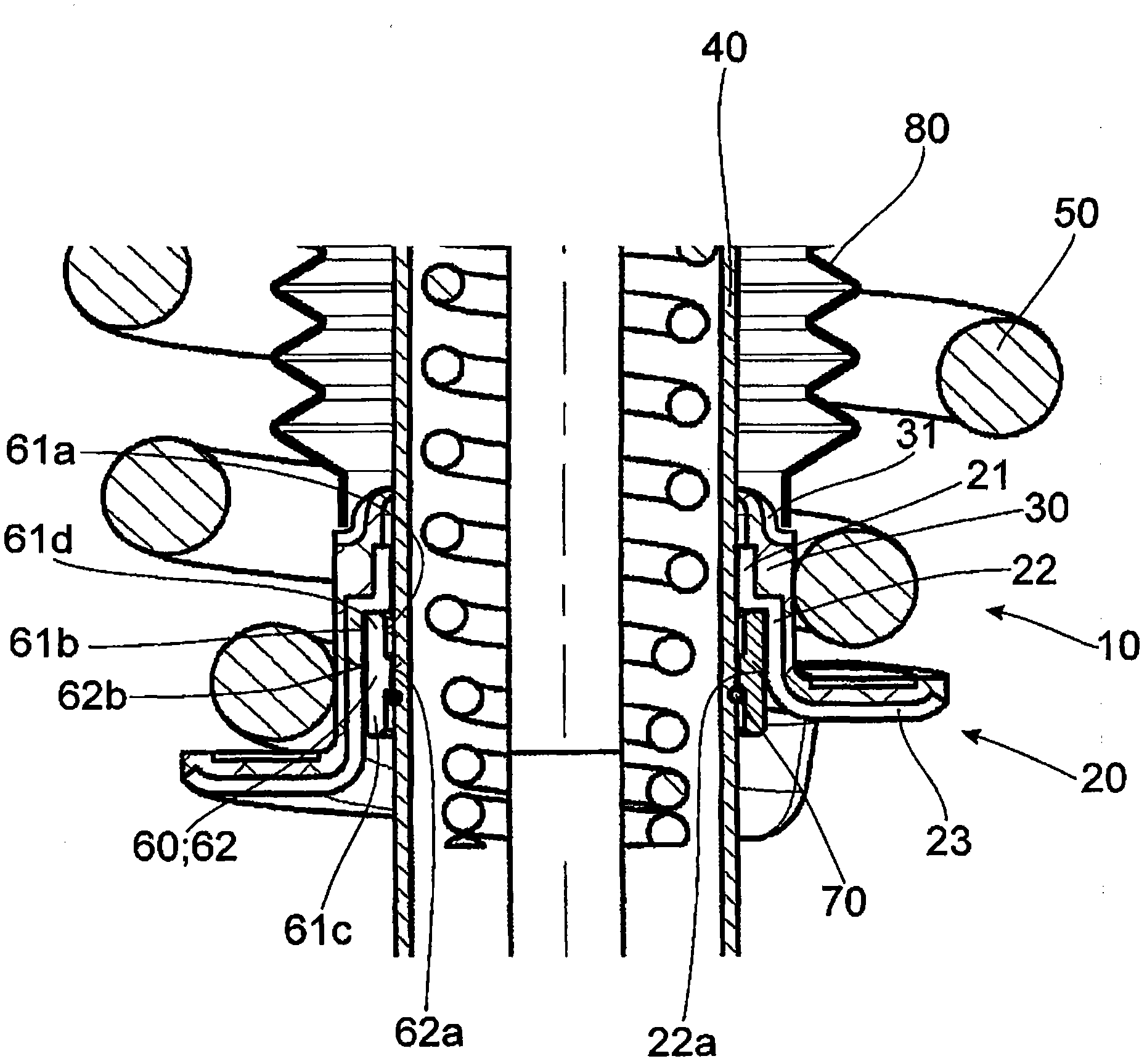
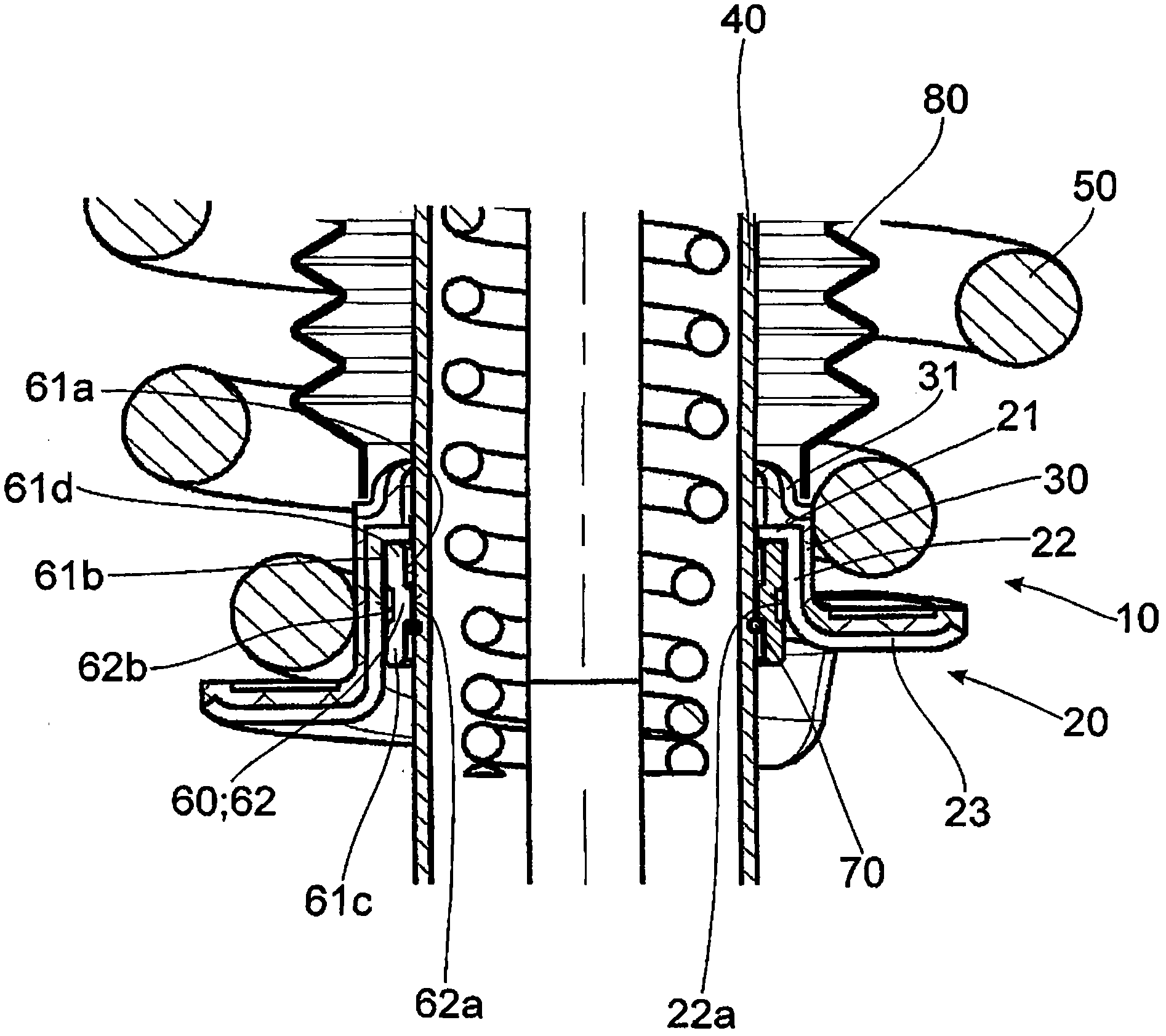
[0028] figure 1 A spring seat fastening device 10 for a shock absorber according to the invention is shown. The spring seat fastening device comprises a spring seat 20 which has a contact section 21 surrounding the damper tube 40 in the circumferential direction. Furthermore, the spring seat 20 has a receiving section 22 axially and radially spaced from the contact section 21 , and a supporting section 23 axially spaced from the contact section 21 . The support section 23 supports the suspension spring 50 in the axial direction by its substantially disk-shaped radial extension. In addition, in figure 1 as well as figure 2 FIG. 3 shows a one-piece spacer element 60 which likewise surrounds the damper tube 40 and is arranged inside the receiving section 22 of the spring seat 20 . figure 2 and Figure 5 The shown separating element 60 is embodied as a sheet metal profile.

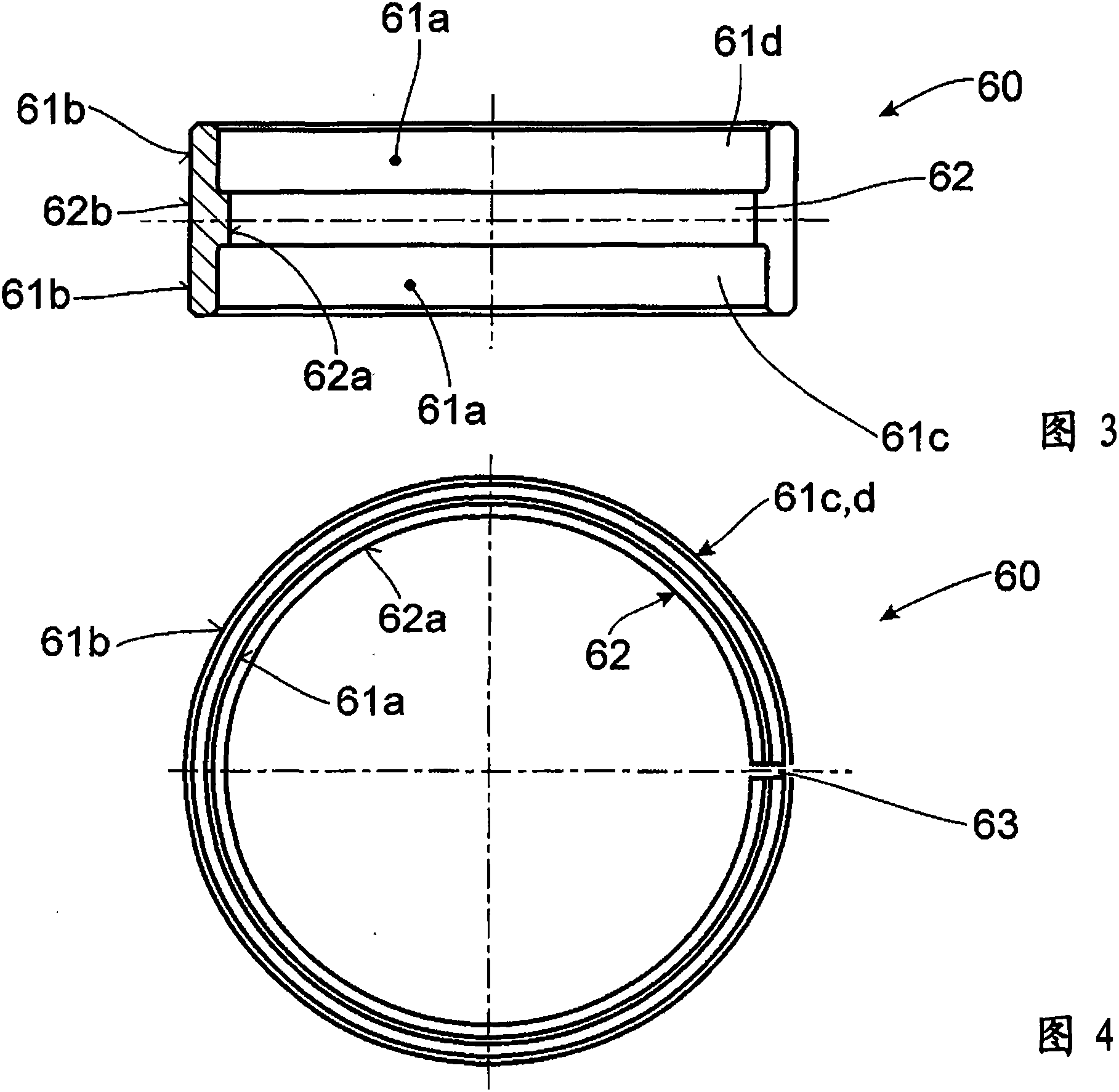
[0029] exist Figure 3 to Figure 5 As can be seen particularly clearly in FIG. 2 , the spacer elem...


PUM


Abstract

The present invention relates to a spring base fixing device (10) for a vibration damper, which comprises a spring base (20). The spring base is provided with the following components: a contact segment (21) which warps a vibration damping tube (40) along a circumferential direction, an accommodating segment (22) which is spaced from the contact segment (21) in an axial direction and a radial direction, and a supporting segment (23) which is spaced from the contact segment (21) in the axial direction, wherein, the supporting segment (23) axially supports a suspension spring (50) through a radial extension part that is basically disc-shaped. Furthermore the spring base fixing device (10) comprises an insulating component (60). The insulating component warps the vibration damping tube (40) and is equipped in the accommodating segment (22) of the spring base (20). Furthermore the insulating component is provided with a first outer segment (61c), a second outer segment (61d) and an intermediate segment (62), wherein, the outer segments (61c,61d) at least partially contact a radial inner surface (21a) of the spring base (20) in the contact segment (21) of the spring base through a radial outer surface (61b). The intermediate segment (62) is equipped between the two outer segments (61c,61d) along the axial direction and the intermediate segment (62) of the insulating component (60) at least partially contacts with the vibration damping tube (40) through a radial inner surface (62a). Furthermore the spring base fixing device (10) is provided with a locking component (70) which coils on the vibration damping tube (40). Furthermore the locking component (70) is radially equipped between the vibration damping tube (40) and a radial inner surface (61a) of one selected from the outer segments (61c,61d) of the insulating component (60) and causes the spring base fixing device (10) to resist the axial load and be locked.

Description

technical field [0001] The invention relates to a spring seat fastening for a shock absorber according to the preamble of claim 1 . Background technique [0002] Spring seat fastenings for shock absorbers of the preceding type are already known in the automotive industry. [0003] The demands placed on the comfort of motor vehicles are now greatly increasing. Furthermore, solutions must now be highly variable and inexpensive and must meet high safety standards. [0004] In order to meet the comfort requirements, the individual vehicle components must be perfectly coordinated with each other. [0005] For example, on cars of the same structural series but with different degrees of motorization, suspension springs are required, whose spring force can meet the comfort requirements of different car model schemes. This can be achieved by using different suspension springs. But this will increase the production cost. Another possibility to change the spring force is to preloa...

Claims


Application Information

Patent Timeline
IPC IPC(8): F16F9/32B60G15/02
CPCF16F2230/24F16F9/3235B60G15/063B60G2204/1242B60G2202/30B60G2202/312
Inventor T・普夫劳姆G・汉德克F・卡尔
Owner ZF FRIEDRICHSHAFEN AG
Why Eureka
Try Eureka