Supercharge Your Innovation With Domain-Expert AI Agents!

Defroster of refrigerator

A technology for refrigerators and condensers, applied in the field of defrosting devices, can solve the problems of reduced efficiency of refrigerators, blocked heat exchange of refrigerator evaporators, and reduced heat exchange efficiency of evaporators, and achieves small temperature fluctuations in the box, low power, and simple structure. Effect

Inactive Publication Date: 2012-07-11
梅宝军
View PDF6 Cites 8 Cited by
  • Summary
  • Abstract
  • Description
  • Claims
  • Application Information

AI Technical Summary

Problems solved by technology

The frost layer will seriously block the heat transfer from the refrigerator evaporator to the freezer and refrigerator; for air-cooled refrigerators, the frost layer will block the air circulation between the fins of the evaporator, which will seriously reduce the heat transfer efficiency of the evaporator; When the thickness of the frost layer reaches a certain value, the efficiency of the refrigerator is seriously reduced, and the refrigerator needs to be defrosted

Method used


Image

  • Defroster of refrigerator
  • Defroster of refrigerator
  • Defroster of refrigerator

Examples


Embodiment 1

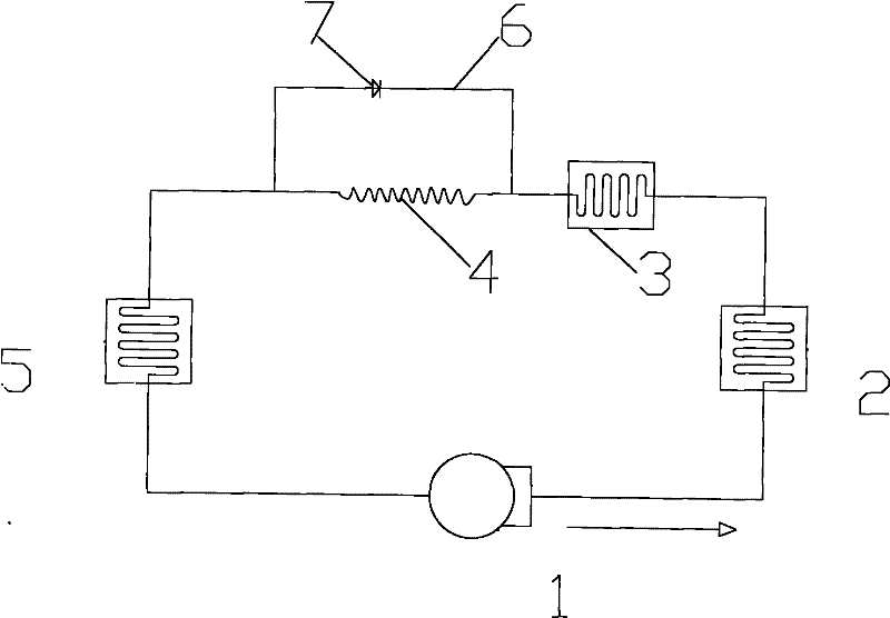
[0021] figure 1 Middle 1 is the refrigerator compressor, 2 is the left condenser of the refrigerator, 3 is the right condenser of the refrigerator, 4 is the capillary tube, 5 is the refrigerator evaporator, 6 is the pipe, and 7 is the valve. In this embodiment, one end of the pipe 6 is connected to the left condenser outlet, the valve 7 is connected to the pipe 6, and the other end of the pipe 6 is connected to the evaporator inlet; when defrosting is performed, the valve 7 is opened, and the pipe 6 will Capillary 4 is short-circuited. When the compressor is turned on, the refrigerant flows out of the right condenser 3 and then enters the evaporator 5 through the pipe 6. Since the pipeline 6 balances the pressure of the evaporator and the condenser, the inlet pressure of the compressor is not much different from the outlet pressure, and the compression ratio of the compressor is small, so the compression work of the compressor is also small. The compressor is like a pump to ma...

Embodiment 2

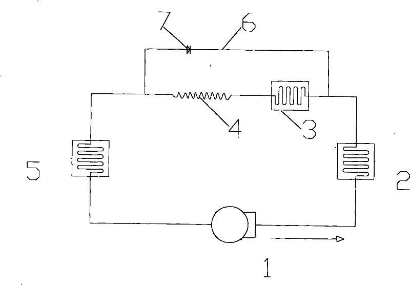
[0023] figure 2 Middle 1 is the refrigerator compressor, 2 is the left condenser of the refrigerator, 3 is the right condenser of the refrigerator, 4 is the capillary tube, 5 is the refrigerator evaporator, 6 is the pipe, and 7 is the valve. The difference between this embodiment and Embodiment 1 is that the inlet end of the pipe in this embodiment is connected with the outlet of the left condenser of the refrigerator, while the inlet end of the pipe in Embodiment 1 is connected with the outlet of the right condenser of the refrigerator.

Embodiment 3

[0025] The refrigerator in this embodiment is a direct-cooling refrigerator. The refrigerator evaporator has a refrigerator compartment evaporator and a freezer compartment evaporator. In this embodiment, one end of the pipe with a valve is connected to the outlet of the refrigerator condenser, and the other end is connected to the refrigerator compartment evaporator. The inlet of the device is connected.


PUM


Abstract

The invention discloses a defroster of a refrigerator. Components mainly including a compressor, a condenser, a capillary tube, an evaporator and the like are arranged on a refrigerating flow of the refrigerator, a condenser of the refrigerator is connected with the evaporator of the refrigerator by a pipeline with a valve, and the valve is electrically connected with a defrosting controller of the refrigerator. During defrosting of the refrigerator, the defrosting controller of the refrigerator controls the valve to be opened, at the moment, the condenser of the refrigerator is communicated with the evaporator, the capillary tube is in short circuit, inlet pressure of the compressor is close to outlet pressure, the compressor mainly realizes effects of a pump to lead refrigerant to circulate, and the circulating refrigerant can absorb heat at the condenser and discharges the heat to defrost at the position of the evaporator. When defrosting is completed, the defrosting controller controls the valve to be closed, and at the moment, the refrigerator runs according to the normal refrigerating flow.

Description

Technical field [0001] The invention relates to a defrosting device for a household refrigerator. technical background [0002] At present, the popularity of refrigerators in our country is very high. Since the temperature of the evaporator in the refrigerator is lower than the dew point of the air in the cabinet, the water vapor in the refrigerator will condense and frost on the surface of the evaporator. The frost layer will seriously block the heat transfer of the refrigerator evaporator to the freezer and refrigerator compartments of the refrigerator; for air-cooled refrigerators, the frost layer will block the air circulation between the evaporator fins, which will seriously reduce the heat exchange efficiency of the evaporator; When the thickness of the frost layer reaches a certain value, the efficiency of the refrigerator is severely reduced, and the refrigerator needs to be defrosted. [0003] At present, the defrosting technology of refrigerators mainly includes several...

Claims


Application Information

Patent Timeline
Patent Type & Authority Applications(China)
IPC IPC(8): F25D21/06F25D29/00F25B41/04
Inventor 梅宝军
Owner 梅宝军
Features
  • R&D
  • Intellectual Property
  • Life Sciences
  • Materials
  • Tech Scout
  • Unparalleled Data Quality
  • Higher Quality Content
  • 60% Fewer Hallucinations
Learn More