
Improved sealing device of circular cooler,

A sealing device and ring cooler technology, which is applied in the direction of engine sealing, mechanical equipment, engine components, etc., can solve the problems of high raw material cost and manufacturing cost, increased production cost, and increased wear of rubber seals.

Inactive Publication Date: 2012-07-11
张志良
View PDF5 Cites 2 Cited by
  • Summary
  • Abstract
  • Description
  • Claims
  • Application Information

AI Technical Summary

Problems solved by technology

Due to the limitation of manufacturing precision, installation and debugging precision, operation precision and other conditions, at present, the sealing element of the ring cooler is generally worn, so that the gap between the two joint surfaces is too large, which greatly affects the sealing effect.
At the same time, due to the high internal ambient temperature of the annular cooler, the temperature can reach above 3-4 degrees, and the high temperature resistance of the sealing material is strictly required, so the raw material cost and manufacturing cost of this material are also high, and the manufacturing accuracy of the equipment is limited. The relative movement between the sealing rubber part and the sealing baffle aggravates the wear of the rubber seal, and the life is limited. The cost and labor cost of replacing the seal itself are as high as hundreds of thousands to one million yuan, which greatly increases production. cost

Method used

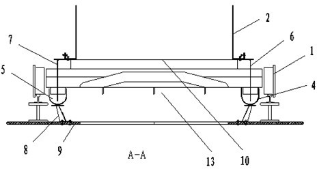

Image

  • Improved sealing device of circular cooler,
  • Improved sealing device of circular cooler,
  • Improved sealing device of circular cooler,

Examples


Embodiment Construction

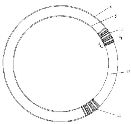
[0023] The present invention is composed of an annular sealing water tank and an annular sealing sliding plate. The annular sealing water groove and the annular sealing sliding plate can have various geometric shapes. The structure is that the annular sealing sliding plate is inserted into the annular sealing water groove, and the annular sealing water groove and the annular sealing sliding plate are installed separately At the lower end of the rotating frame 2 of the trolley 1 and below the trolley shaft, the water level difference between the left and right sides of the sealing slide plate in the sealing water tank is used to overcome (or offset) the wind pressure of the internal cooling fan of the ring cooler to achieve the ring cooler The purpose of sealing and cooling, therefore, any water sealing device designed based on this structural concept should belong to the protection scope of the present invention.

[0024] The figure shows that the basic structure of the present in...


PUM


Abstract

The invention discloses an improved sealing device of a circular cooler, which belongs to the technical field of iron-making sintering equipment and is used for improving the sealing of the sintered-ore circular cooler. The technical scheme is as follows: the improved sealing device comprises lower sealing water grooves and lower sealing sliding plates, wherein the lower sealing water groove is a ring-shaped water groove; the lower sealing sliding plates are of a circular shape consisting of a plurality of sections of ring-shaped pieces; the circumferential diameter of the ring-shaped pieces of the lower sealing sliding plate is matched with that of the center of the lower sealing water grooves; a lower sealing water sliding plate is fixedly arranged at the lower end of a rotary frame and below a trolley shaft; the lower sealing water grooves are fixed below the rotary frame; trolley operating guide rails are positioned above an installation base; the lower sealing sliding plates are inserted into the lower sealing water grooves which are connected with a water supplementing device and a water recovering device. The improved sealing device has the obvious advantages of no wear for sealing pieces, simplicity in manufacture, reliability in working, convenience in maintenance and obvious economic benefit.

Description

Technical field [0001] The invention relates to a sealing device for a sintered ore ring cooler, belonging to the technical field of ironmaking and sintering equipment. Background technique [0002] In steel production enterprises, sintering is one of the ironmaking processes. The process is to mix powdered ore powder and coke powder through a sintering machine to make them into particles of a certain size to facilitate smelting. The sintered ore passing through the sintering machine needs to be cooled, and the cooling is mainly achieved through the air cooler below. At present, the cooling machines used by iron and steel enterprises have two forms: belt cooling and annular cooling. The annular cooling machine is widely used by most steel production enterprises because of its compact structure, small floor space and recyclable loading trolley. [0003] In order to improve the cooling effect, the trolley carrying sintered ore needs to be operated in a relatively closed environment ...

Claims


Application Information

Patent Timeline
IPC IPC(8): F27D15/02F16J15/40
Inventor 张志良杨健
Owner 张志良
Learn More