Test device for testing flow characteristics of liquefied sand and test method

A technology of flow characteristics and test equipment, which is applied in the field of geotechnical earthquake engineering, can solve problems such as inapplicable apparent viscosity, exceeding the measurement range, and unable to flow smoothly, so as to avoid boundary effects and local effects, improve test efficiency, and avoid measurement effect of error

Active Publication Date: 2012-07-11
HOHAI UNIV
View PDF5 Cites 18 Cited by
  • Summary
  • Abstract
  • Description
  • Claims
  • Application Information

AI Technical Summary

Problems solved by technology

However, none of the above-mentioned viscosity measurement methods can effectively measure the apparent viscosity of liquefied sand, and the movement state of sand particles cannot be observed during the measurement process. The reasons are:
[0004] (1) The falling ball viscometer requires the fluid to remain in a static state, while the liquefaction of saturated sand is produced under the action of dynamic load, and the liquefied sand is in a state of motion, so the traditional falling ball viscometer is not suitable for the liquefaction state of saturated sand Measurement of apparent viscosity under
[0005] (2) The capillary viscometer needs to use a slender glass tube, and the rotational viscometer requires the fluid to flow in shear in the slit, and sand is a material with a certain particle size, which cannot flow smoothly in the slender glass tube or slit , so the apparent viscos

Method used


Image

  • Test device for testing flow characteristics of liquefied sand and test method
  • Test device for testing flow characteristics of liquefied sand and test method
  • Test device for testing flow characteristics of liquefied sand and test method

Examples


Embodiment Construction

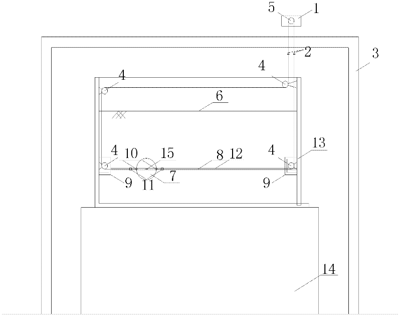
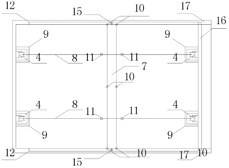
[0050] Such as figure 1 , figure 2 As shown, a test device for testing the flow characteristics of liquefied sand, including a vibrating table (14) and a model box (13) fixed on the vibrating table, also includes a low-speed adjustable motor (1), a dynamic displacement sensor (2) , fixed pulley (4), bearing (5), rigid round tube (7), small pulleys on both ends of the rigid round tube (15), steel wire rope (8), fixed pulley protection box (9), dynamic hole pressure sensor (10 ), dynamic tension sensor (11), plastic panel track (12), detachable panel (16) and plastic panel (17). The excitation direction of the vibrating table (14) is perpendicular to the direction of the plastic panel (12).

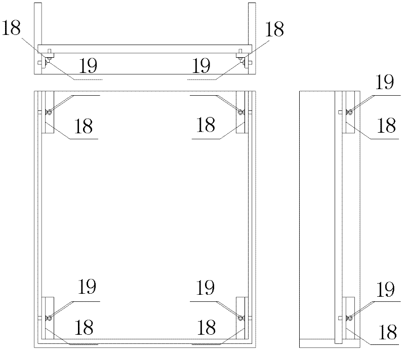
[0051] The plastic panel track (12) can be excavated on the plastic panel (16) by tools, and the excavated track surface is polished and smoothed. The detachable panel (17) is connected with the model box (13) by way of card slots, such as image 3 As shown, a card slot with a depth of...


PUM


Abstract

The invention discloses a test device for testing flow characteristics of liquefied sand and a test method. The device comprises a vibration platform and a model box. Plastic face plates are adopted on two lateral faces of the model box, a horizontal rail is respectively arranged at the symmetrical positions of the plastic face plates, and a rigid circular pipe is placed between the rails. A steel wire rope is led out from the rigid circular pipe and connected with and pulls a force sensor, leads out the model box, then is connected with a dynamic displacement sensor, and finally is connected to a positive and reverse speed regulation motor. The test method comprises enabling saturated sand in the model box to achieve a liquefied state through the vibration platform, the motor drives the steel wire rope and then guides the rigid circular pipe to perform horizontal movement on the rails to measure the speed of the movement of the rigid circular pipe and horizontal tension force exerted on the rigid circular pipe, so that apparent viscosity of the liquefied sand is calculated, and the flow characteristics of the liquefied sand are analyzed. The test device for testing flow characteristics of the liquefied sand and the test method has the advantages of being high in efficiency, small in boundary effect and the like.

Description

technical field [0001] The invention belongs to the technical field of geotechnical earthquake engineering, in particular to a test device and a test method for testing the flow characteristics of liquefied sandy soil. Background technique [0002] Earthquake is one of the main natural disasters faced by human beings. In earthquake disasters, the engineering hazards caused by sand liquefaction are attracting more and more attention. This makes the dynamic characteristics of sand liquefaction become a new field of geotechnical research. Research hotspots. The total stress of saturated sand is composed of effective stress and pore water pressure. In general, the load of the foundation is mainly borne by the effective stress in the total stress. However, when an earthquake occurs, the pore water in the saturated sand The pressure will continue to rise under the action of the seismic load, and under the premise that the total stress remains constant, the effective stress will c...

Claims


Application Information

Patent Timeline
IPC IPC(8): G01N11/12
Inventor 陈育民周葛丁选明刘汉龙高星
Owner HOHAI UNIV
Why Eureka
Try Eureka