Cell sorter and cell sorting method

A sorter and cell technology, which is applied in the field of cell sorter and cell sorting, can solve the problems of different cell flow rates and the cells will not be reliably sorted, and achieve the effect of reliable sorting

Active Publication Date: 2012-07-11
SONY CORP
View PDF6 Cites 7 Cited by
  • Summary
  • Abstract
  • Description
  • Claims
  • Application Information

AI Technical Summary

Problems solved by technology

[0006] However, in this case, every time the channel design is changed, it is necessary to set the delay time
Also, in practice, cell flow rates may vary due to cell structure, shape, size, and other factors
Therefore, cells may not be reliably sorted in the case of cell sorting in a given delay time

Method used


Image

  • Cell sorter and cell sorting method
  • Cell sorter and cell sorting method
  • Cell sorter and cell sorting method

Examples


Embodiment Construction

[0034] Hereinafter, preferred embodiments of the present invention will be described with reference to the drawings.

[0035] 〔Structure of a cell analysis / sorting system〕

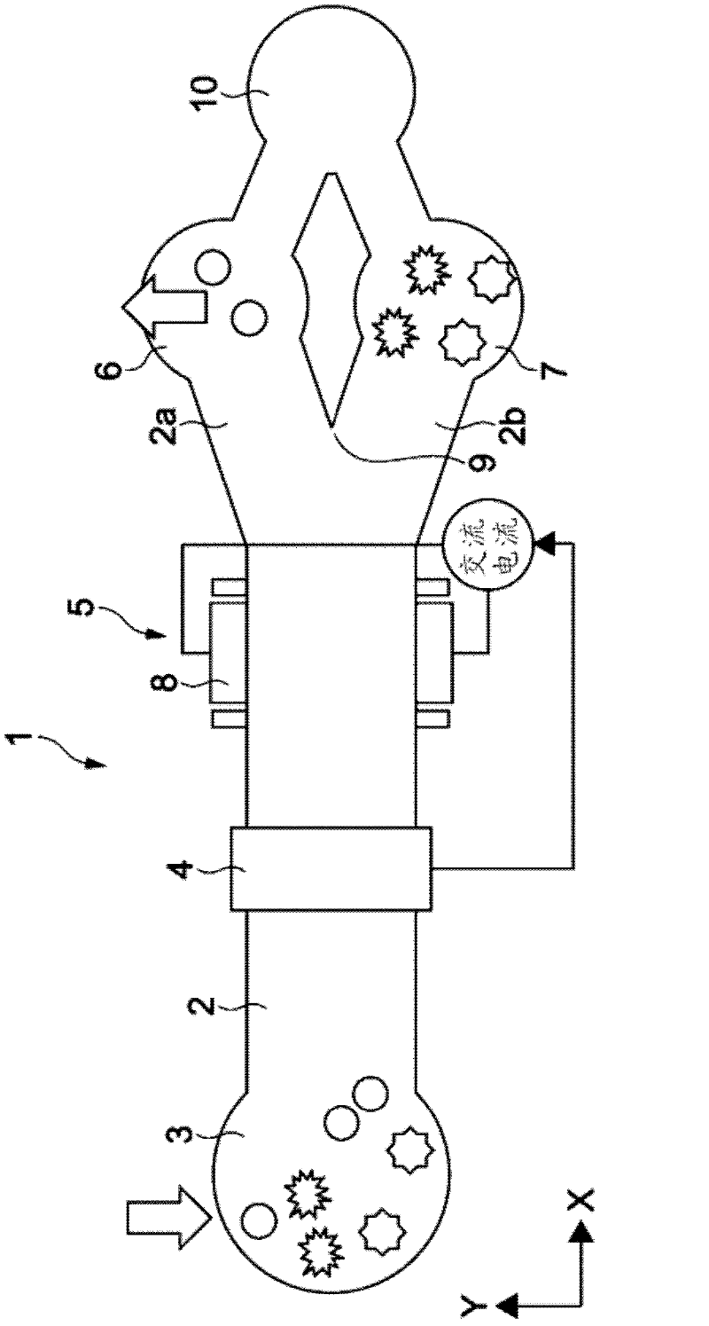
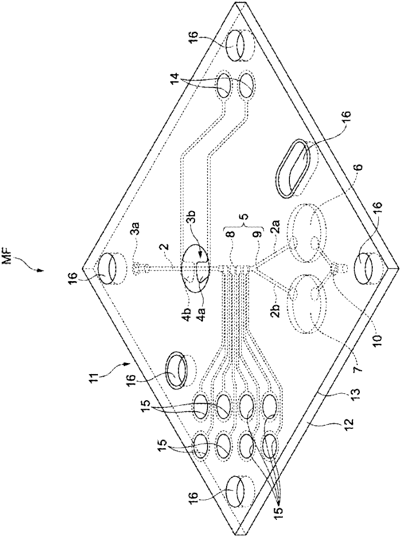
[0036] figure 1 It is a conceptual diagram showing a cell analysis / sorting system according to one embodiment of the present invention. figure 2 is the composition figure 1 A perspective view of a microfluidic device that is a part of the cell analysis / sorting system 1 shown.

[0037] Such as figure 1 As shown, an injection unit 3 , a measurement unit 4 , a sorting unit 5 , cell extraction units 6 and 7 , and an outflow unit 10 are sequentially arranged from upstream along the flow channel 2 formed in the micro flow channel device MF.

[0038] The sampling liquid (fluid) including cells is injected into the injection part 3 using, for example, a pump not shown.

[0039] The liquid injected from the injection part 3 flows through the flow path 2 .

[0040] The measuring unit 4 measures the complex...


PUM


Abstract

The invention relates to a cell sorter and a cell sorting method. The cell sorter includes a measuring electrode, a working electrode, a detection electrode, and an output section. The measuring electrode forms a measuring electric field in a flow path to measure a complex dielectric constant of each cells flowing through the flow path. The working electrode forms, in the flow path, a working electric field to sort the cells by imparting a dielectrophoretic force to the cells and using the flow path. The detection electrode detects the presence of the cell in the fluid flowing through the flow path. The output section acquires a sorting signal based on information about the measured complex dielectric constant and a detection signal indicating the detection of the cell by the detection electrode. The output section outputs a working signal adapted to form the working electric field to the working electrode when the detection signal is acquired if the sorting signal is acquired.

Description

technical field [0001] The invention relates to a cell sorter and a cell sorting method for sorting cells. Background technique [0002] In the prior art, a dielectric cell counting device is proposed that measures the inherent complex permittivity of cells and uses the measurement result information to sort cells (for example, refer to Patent Document 1, Japanese Patent No. 2010-181399, Figure 3 ~ Figure 5 ). [0003] Patent Document 1 discloses a flow channel device for passing a fluid including cells therethrough in order to analyze the cells before cell sorting to obtain a complex dielectric constant, for example. A constricted portion is formed on a part of the flow path formed in the flow path device. The constriction has a channel cross-sectional area so small that only a single cell can pass through it. Measuring the distribution (dielectric spectrum) of the complex permittivity of each cell passing through the constriction, so that cells can be sorted downstream ...

Claims


Application Information

Patent Timeline
Patent Type & Authority Applications(China)
IPC IPC(8): G01N15/10
CPCB03C5/005B03C5/026
Inventor 佐藤一雅胜本洋一
Owner SONY CORP
Why Eureka
Try Eureka