

Method and device for performing pseudorange observation estimation by carrier smoothing
A pseudo-range observation, smoothing pseudo-technology, applied in the field of navigation, can solve the problem of large pseudo-range error, multi-path and measurement noise suppression effect.
- Summary
- Abstract
- Description
- Claims
- Application Information
AI Technical Summary
Problems solved by technology
Method used
Image


Examples
Embodiment 1
[0112] Embodiment 1, a method for estimating pseudorange observations by carrier smoothing, comprising:
[0113] Obtain the pseudorange and carrier phase observations of n frequency points respectively; n is an integer greater than or equal to 2;
[0114] Perform the carrier smoothing pseudorange operation at each frequency point at the same time to obtain the smoothed pseudorange ;
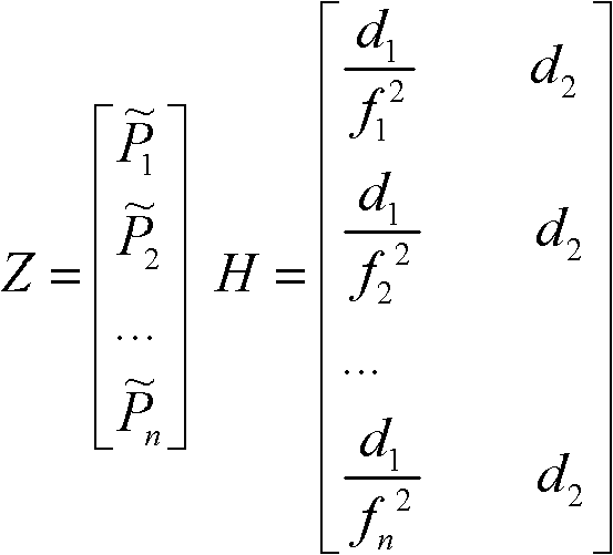
[0115] The smoothed pseudoranges of multiple frequency points are formed into a measurement equation:
[0116] Z=HX+V;(33)
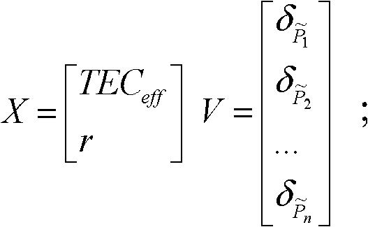
[0117] in:
[0118] Z = P ~ 1 P ~ 2 . . . ...
Embodiment 2
[0156] Embodiment 2. A device for estimating pseudorange observations by carrier smoothing, such as figure 1 shown, including:
[0157] The measurement module is used to obtain the pseudorange and carrier phase observations of n frequency points respectively; n is an integer greater than or equal to 2;
[0158] The smoothing module is used to perform the carrier smoothing pseudorange operation at each frequency point at the same time to obtain the smoothed pseudorange ;
[0159] The building block is used to form a measurement equation from the smoothed pseudoranges of multiple frequency points:
[0160] Z=HX+V;(33)
[0161] in:
[0162] Z = P ~ 1 P ~ 2 ...
PUM
 Abstract
Description
Claims
Application Information