Light source device, method for generating light source, and laser projector including light source device

A light source device and light source technology, applied in the field of laser projection, can solve the problems of laser energy loss, undisclosed, no adjustment and support device, etc., and achieve the effects of reducing the number of optical components, reducing energy loss, and simplifying the manufacturing process

Active Publication Date: 2014-10-29
HISENSE
View PDF6 Cites 0 Cited by
  • Summary
  • Abstract
  • Description
  • Claims
  • Application Information

AI Technical Summary

Problems solved by technology

But, the technical scheme in CN101872071 is only for the situation of the laser beam of small emission full-angle, can not be applicable to the situation of the laser beam of large emission full-angle
For example, the existing technical solutions cannot ensure that the diameter of the obtained surface light source is on the order of tens of millimeters, that is, the surface light source output by the aforementioned collimating optical lens group cannot meet the requirements of the laser projector for the input light source
[0008] In addition, CN101872071 simply gives the parameters and positional relationship of each optical element, but does not disclose any means to ensure such parameters and positional relationship
When the aforementioned parameters and positional relationship are on the order of millimeters, especially when the accuracy of some parameters needs to reach the hundredth or even the thousandth, without effective adjustment and support devices, such accuracy cannot be guaranteed at all.
In the case of deviations in parameters and positional relationships, the energy of the laser may be greatly consumed, resulting in low light utilization
[0009] Furthermore, in the scheme disclosed in CN101872071, the semiconductor laser 10 must pass through the optical fiber 11 to transmit the laser pulse signal to the collimating lens group 12, and the various processing and transmission of the laser pulse signal in the optical fiber 11 will be to a certain extent Lead to loss of laser energy, which further reduces light utilization
Moreover, in order to ensure the normal transmission of the laser pulse signal, the installation position and accuracy of the semiconductor laser 10, the optical fiber 11 and the collimator lens group 12 must be strictly controlled, the installation process is relatively complicated, and the existence of many components is easy to cause the accumulation of matching errors , which in turn affects the overall quality of the output surface light source

Method used


Image

  • Light source device, method for generating light source, and laser projector including light source device
  • Light source device, method for generating light source, and laser projector including light source device
  • Light source device, method for generating light source, and laser projector including light source device

Examples


Embodiment Construction

[0053] The technical solutions of the various embodiments of the present invention will be clearly and completely described below in conjunction with the accompanying drawings. Apparently, the described embodiments are only some of the embodiments of the present invention, not all of them. Based on the embodiments of the present invention, all other embodiments obtained by persons of ordinary skill in the art without making creative efforts belong to the protection scope of the present invention.

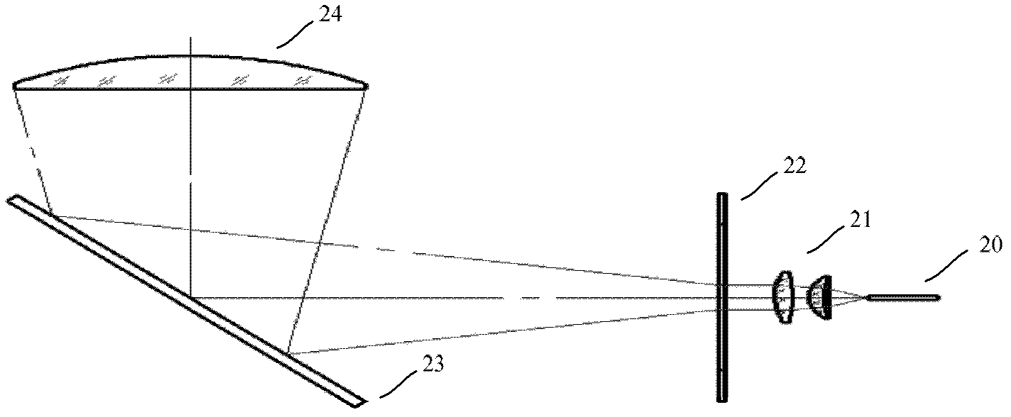
[0054] figure 2 is an exemplary schematic diagram of a light source device according to an embodiment of the present invention. Such as figure 2 As shown, the light source device in the implementation of the present invention includes a laser 20 , a first collimating component 21 , a scattering component 22 , a reflecting component 23 and a second collimating component 24 .

[0055] Wherein, the laser 20 is used for emitting a laser beam traveling along a first direction. The f...


PUM


Abstract

The invention discloses a light source apparatus, a light source generation method and a laser projector containing the light source apparatus. The light source apparatus comprises a first collimation part, a scattering part, a reflecting part and a second collimation part. The first collimation part carries out first collimation processing on a laser beam which is transmitted along a first direction, and a laser beam with an emission full angle less than or equal to a first angle threshold is obtained and is emitted along the first direction. The scattering part carries out speckle removal processing on the laser beam which goes through the first collimation processing, and the laser beam is emitted along the first direction. The reflecting part reflects a received laser beam, and a laser beam emitted along a second direction is obtained. The second collimation part carries out second collimation processing on a received laser beam to obtain a laser beam with an emission full angle which is larger than or equal to a second angle threshold and less than or equal to a third angle threshold. According to the light source apparatus, the light source generation method and the laser projector, an input light source used by the laser projector can be effectively obtained, and since a fiber is omitted, utilization rate of light is high.

Description

technical field [0001] The invention relates to laser projection technology, in particular to a light source device, a method for generating a light source and a laser projector including the light source device. Background technique [0002] In recent years, laser projectors have been widely used in various occasions due to their simple principle, low manufacturing difficulty, rich colors, and small visual impact. However, the input light source required by the laser projector is a surface light source, and it has higher requirements for the input surface light source. For example, for some laser projectors, the input surface light source can only be a surface light source with a diameter on the order of tens of millimeters. Therefore, how to obtain a good input light source has become an important issue in the development of laser projection technology. [0003] At present, the laser generator is used as the original light source of the laser projector, and the point lig...

Claims


Application Information

Patent Timeline
Patent Type & Authority Patents(China)
IPC IPC(8): G03B21/20G02B27/48G02B27/30F21V13/04
Inventor 王自上李巍陈昱刘风雷
Owner HISENSE
Why Eureka
Try Eureka