Magnetic levitation device with function of automatically lifting suspended matter

A technology for automatic lifting and suspension of objects, applied in the direction of magnetic attraction or thrust holding devices, electrical components, etc., can solve the problems of difficult display methods, affecting the suspension effect, and delaying time, so as to improve work stability and simple and compact structure , Guarantee the effect of the effect

Inactive Publication Date: 2012-07-11
中磁力(深圳)科技有限公司
4 Cites 29 Cited by

AI-Extracted Technical Summary

Problems solved by technology

However, this manual way of storing suspended solids is relatively difficult. It depends entirely on the experience and feel of the operator. For su...

Method used

As shown in Fig. 1 and Fig. 2, the magnetic levitation device that the present invention has suspended matter automatic lifting function, comprises magnetic levitation assembly 4, and magnetic levitation assembly 4 is used for under energized state, utilizes magnetic levitation principle that levitation matter 7 is floated on it . The position corresponding to the levitation object 7 on the magnetic levitation assembly 4 is provided with a lifting assembly, that is, a through hole can be opened on the base of the magnetic levitation assembly 4, the lifting assembly is arranged under the base and extends, penetrates in the through hole, and passes through the through hole. Cooperate with the suspension 7 after the hole. The lifting assembly in the present invention includes a pallet frame 6 , a lifting column 5 , a lifting transmission component and a control unit. The pallet frame 6 is located at the bottom of the suspended object 7 and can support the suspended object 7 after being in contact with the suspended object 7 . One end of the lifting column 5 is connected with the tray frame 6, and the other end of the...

Abstract

A magnetic levitation device with the function of automatically lifting a suspended matter comprises a magnetic levitation component; a lifting component is arranged on the magnetic levitation component and at the position corresponding to the suspended matter; the lifting component comprises a pallet rack, a lifting column, a lifting transmission component and a control unit; the pallet rack is positioned at the bottom of the suspended matter; one end of the lifting column is connected with the pallet rack, and the other end of the lifting column is connected with the output end of the lifting transmission component; and the control terminal of the lifting transmission component is connected with the control unit. The magnetic levitation device has the advantages of simple and compact structure, low cost, high degree of automation, simplicity and convenience in operation, stability and reliability in working, and the like.

Application Domain

Magnetic holding devices

Technology Topic

Image

  • Magnetic levitation device with function of automatically lifting suspended matter
  • Magnetic levitation device with function of automatically lifting suspended matter
  • Magnetic levitation device with function of automatically lifting suspended matter

Examples

  • Experimental program(1)

Example Embodiment

[0022] The present invention will be further described in detail below with reference to the drawings and specific embodiments of the specification.
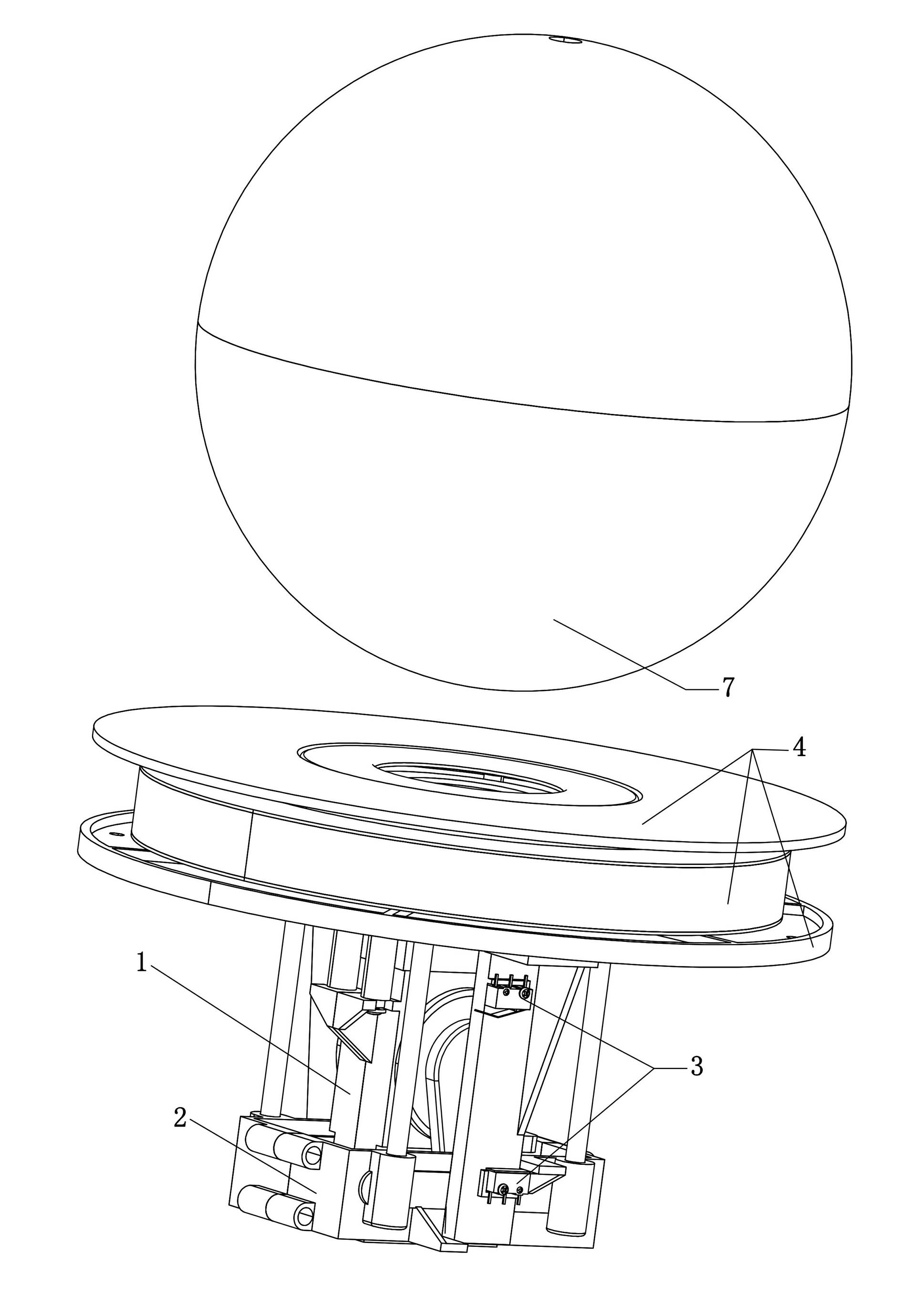
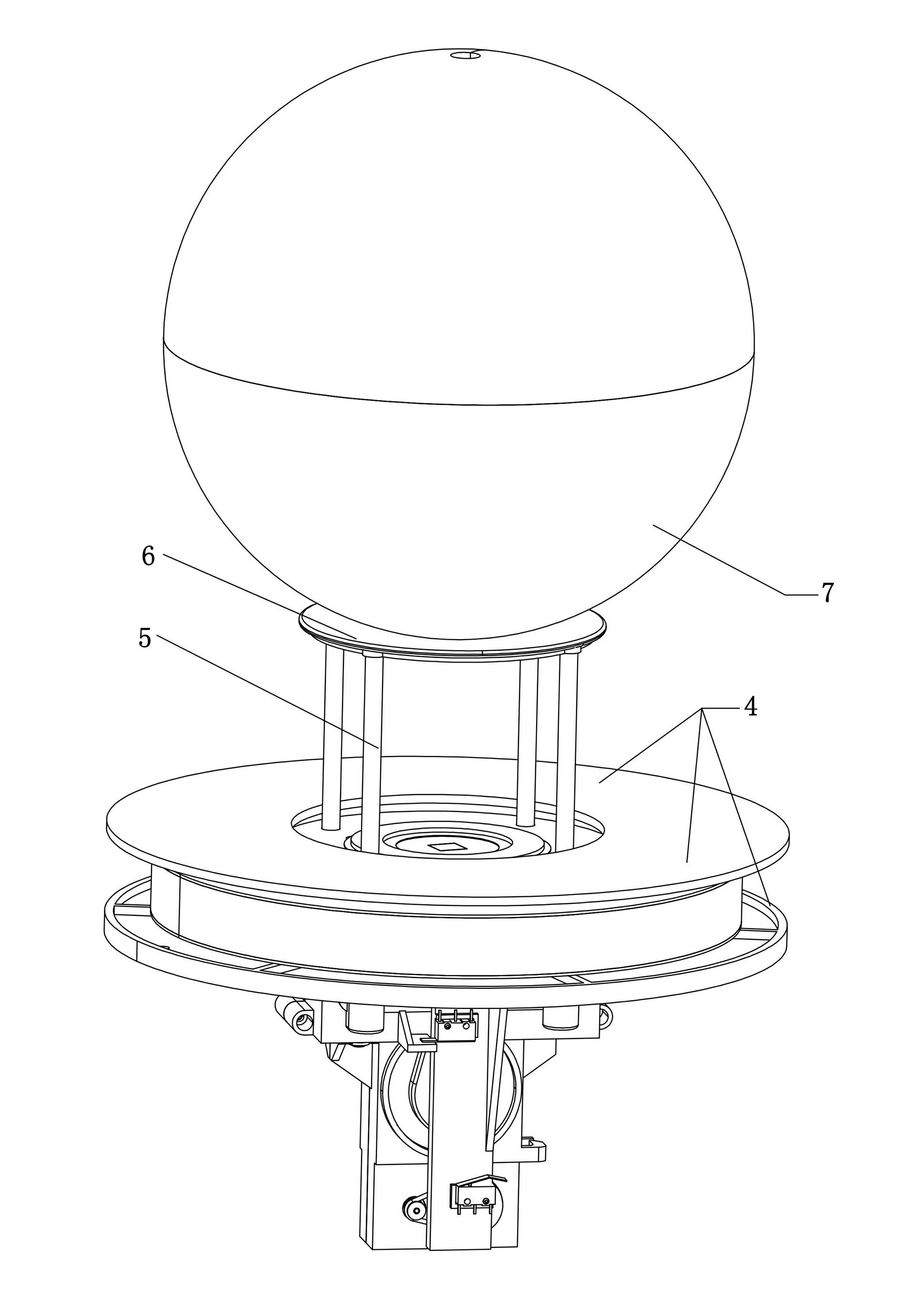
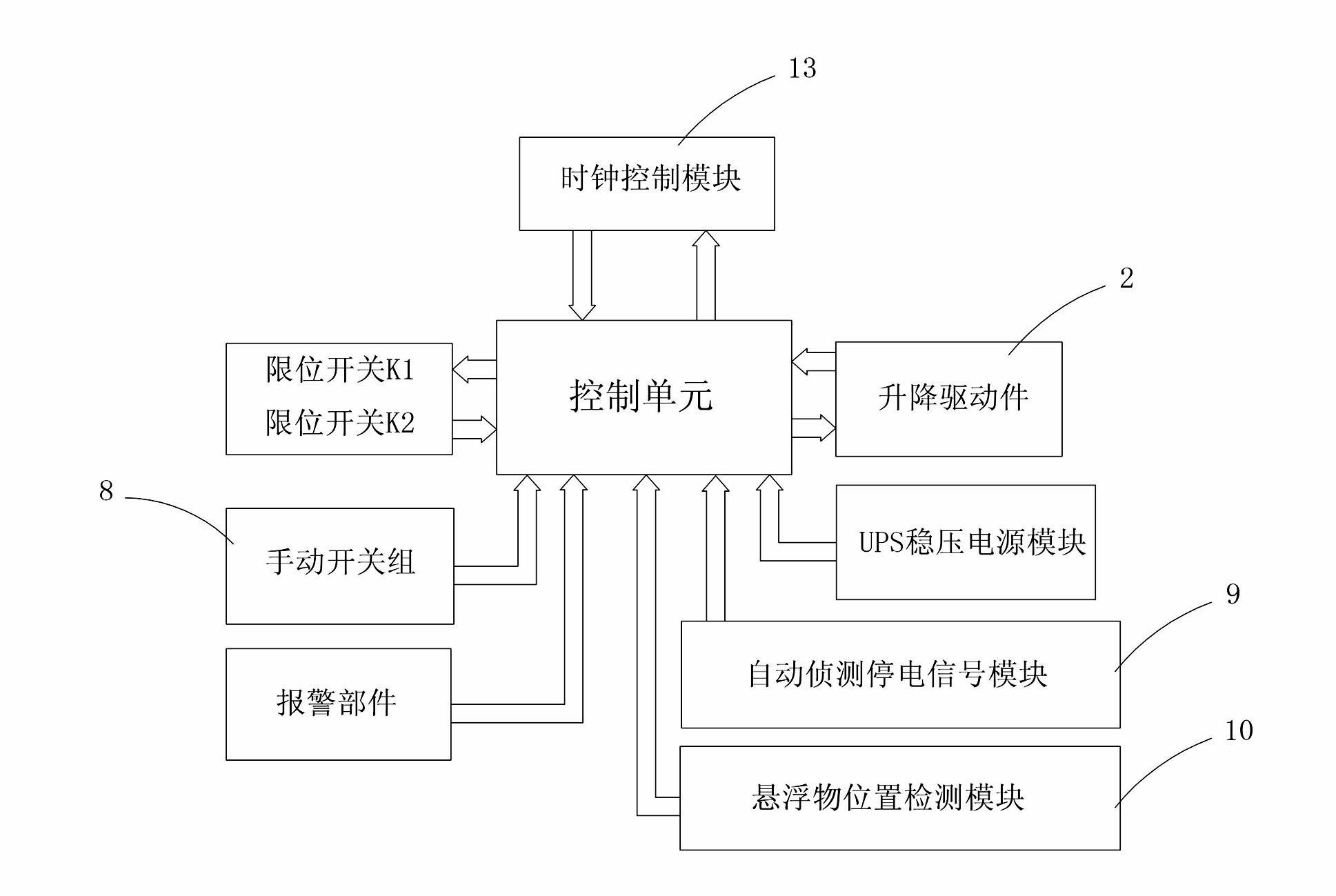
[0023] Such as figure 1 with figure 2 As shown, the magnetic levitation device with the function of automatic lifting of suspended objects of the present invention includes a magnetic levitation component 4, which is used to float the suspended object 7 on it by using the principle of magnetic levitation when the power is on. The magnetic levitation component 4 is provided with a lifting component at a position corresponding to the suspended object 7, that is, a through hole can be opened on the base of the magnetic levitation component 4, and the lifting component is arranged under the base and extends and penetrates through the through hole. Match with suspended solid 7 after the hole. The lifting assembly in the present invention includes a tray frame 6, a lifting column 5, a lifting transmission component and a control unit. The tray frame 6 is located at the bottom of the suspended object 7 and can support the suspended object 7 after being in contact with the suspended object 7. One end of the lifting column 5 is connected to the tray frame 6, and the other end of the lifting column 5 is connected to the output end of the lifting transmission component. The lifting column 5 can be a carbon rod column to achieve the purpose of firmness. The control end of the lifting transmission component is connected with the control unit. Under the control of the control unit, the lifting transmission component can carry the lifting column 5 and the tray frame 6 for lifting movement.
[0024] In this embodiment, combining image 3 As shown, the control unit includes a manual switch group 8, which is connected to the lifting transmission component and completes the switching of the lifting, lowering and stopping working states of the lifting transmission component. In the initial stage of the operation of the magnetic levitation assembly 4, the suspended object 7 can be placed on the pallet rack 6, the manual switch group 8 is turned on, and the lifting transmission member moves the suspended object 7 to a suitable magnetic levitation position. The function is turned on, the suspended object 7 is floated in the air by magnetic levitation technology, and then the lifting transmission component is controlled by the manual switch group 8 to bring the tray frame 6 down.
[0025] In this embodiment, see image 3 As shown, the control unit also includes an automatic detection power failure signal module 9 for real-time detection of the power supply status of the magnetic levitation component 4. The automatic detection power failure signal module 9 is connected to the lifting transmission component and completes the switching of the lifting and lowering working status of the lifting transmission component . In the event of a power failure or insufficient backup power, the automatic detection of power failure signal module 9 will automatically detect the power failure signal, so that the lifting transmission components start to work, drive the tray rack 6 up, and lift the suspended objects 7 to prevent the suspended objects 7 from being caused by the outside world. It will directly fall due to power failure, so as to achieve the purpose of protecting suspended solids 7. When a call comes in, the automatic detection of power failure signal module 9 will automatically detect the electrical signal, and the lifting transmission component starts to work and is in a landing state. When the suspended matter 7 falls to the levitation height of the magnetic levitation assembly 4, the suspended matter 7 is automatically lifted and floated in the air by using the magnetic levitation technology, so that the magnetic levitation product needs to be re-aged after the power failure.
[0026] In this embodiment, the present invention further includes a suspended object position detection module 10 connected to the control unit. The suspended object position detection module 10 is used to detect in real time whether there is suspended object 7 on the magnetic levitation assembly 4 and whether the suspended object 7 is located on the tray rack. 6 is at the geometric center point. The suspended object position detection module 10 includes a detection component and an alarm component. The alarm component is used to sound an alarm when it detects that there is no suspended object 7 on the magnetic levitation assembly 4 or the suspended object 7 is not at the geometric center position of the pallet rack 6, and controls After receiving the signal from the suspended object position detection module 10, the unit will stop the movement of the lifting transmission component to ensure the stability of the suspended object 7 when it is descending. Its working process: when there is no suspended object 7, the suspended object position detection module 10 can automatically recognize that the lifting device rises in the state of waiting for the suspended object 7, and the alarm component emits a "beep..." alarm sound as a reminder; After the suspended object 7 is put in, the suspended object position detection module 10 automatically recognizes whether the storage position of the suspended object 7 is at the correct position of the center point of the pallet rack 6; if it is at the center point, the alarm sound of the alarm component 12 stops. Automatically descend to a suspended state. When the suspended object position detection module 10 recognizes that the suspended object 7 is stored in a wrong position and is not at the midpoint position, the alarm component will continue to emit a "beep..." alarm sound as a reminder until it is placed correctly, the alarm sound Stop and make it automatically descend to the state of suspension.
[0027] In this embodiment, it further includes a clock control module 13, which is connected to the control unit and is used to increase the clock control function. The rising time and the falling time are set by the clock control module 13 and executed according to the confirmation. The unit will output control signals to the lifting drive to complete the lifting process. That is, the user can set the time arbitrarily to control the lifting time point, to satisfy the customer that the magnetic levitation is not working or in the standby state during certain periods of time, which has achieved the purpose of energy saving and extending product life. For example, the user needs to be in the standby state from 12 pm to 6 am, and the time can be set through the clock control module 13 to realize this function.
[0028] In this embodiment, the lifting transmission component includes a gear box 1 and a lifting drive member 2. The output end of the lifting drive member 2 is connected to the lifting column 5 through the gear box 1 and can drive the lifting column 5 to perform lifting motion. The lifting column 5 is provided with Lifting height limit switch 3. The lifting driving member 2 can be a DC motor or other forms of motor, and the matching noise between the motor and the gear box 1 is small, and the transmission is relatively stable. Of course, in other embodiments, other forms of lifting drive 2 and transmission components, such as electric motors, hydraulic motors, chain transmissions, rack and pinion transmissions, etc., can also be used according to actual needs.
[0029] The above are only the preferred embodiments of the present invention, and the protection scope of the present invention is not limited to the above-mentioned embodiments. All technical solutions under the idea of ​​the present invention belong to the protection scope of the present invention. It should be noted that for those of ordinary skill in the art, several improvements and modifications without departing from the principle of the present invention should be regarded as the protection scope of the present invention.

PUM

no PUM

Description & Claims & Application Information

We can also present the details of the Description, Claims and Application information to help users get a comprehensive understanding of the technical details of the patent, such as background art, summary of invention, brief description of drawings, description of embodiments, and other original content. On the other hand, users can also determine the specific scope of protection of the technology through the list of claims; as well as understand the changes in the life cycle of the technology with the presentation of the patent timeline. Login to view more.

Similar technology patents

Classification and recommendation of technical efficacy words

  • Simple and compact structure
  • Low cost

Opening-nozzle saddle-shaped seam welding equipment

Owner:BEIJING INSTITUTE OF PETROCHEMICAL TECHNOLOGY

System and method for transmitting wireless digital service signals via power transmission lines

ActiveUS7929940B1Reduce bandwidth requirementLow costInterconnection arrangementsWireless systems/telephoneElectric power transmissionBase transceiver station
Owner:NEXTEL COMMUNICATIONS

Nanowire structures comprising carbon

ActiveUS20070212538A1Low costImproved electrical connectivity and stabilityElectric discharge heatingFuel cells groupingNanometreMembrane configuration
Owner:ONED MATERIAL INC
Why Eureka
Try Eureka