Radio frequency matching method and device, as well as plasma device

A radio frequency matching and plasma technology, applied in the direction of plasma, electrical components, etc., can solve the problems of the matcher not working properly, precision impact, low precision, etc., to simplify the operation type and operation time, stable and accurate matching, and improve measurement accuracy Effect

Active Publication Date: 2012-07-11
BEIJING NAURA MICROELECTRONICS EQUIP CO LTD
View PDF7 Cites 10 Cited by
  • Summary
  • Abstract
  • Description
  • Claims
  • Application Information

AI Technical Summary

Problems solved by technology

[0010] like figure 1 As shown, the existing sensor uses a multiplier to obtain the sensor output value and sends the sensor output value to the controller, and the controller obtains the corresponding M according to the above sensor output value 3×3 matrix such that the sensor signal A 3×1 There is a non-linear relationship with the three variables of voltage amplitude |V|, current amplitude |I| and phase α, so complex operations such as multiplication are inevitably used in the process of solving |V|, |I|, α, resulting in Acquisition time greatly increased
And because there are many parameter variables, the uncertainty of the final result increases, which has a great impact on the accuracy.
Corresponding to the same input impedance, when a certain variable is greatly disturbed, the obtained input impedance will be greatly affected, which may cause a large error
The sensor with the above characteristics will cause the matching path of the actuator in the matcher to be poor, take a long time, and have low precision, and even cause the matcher to not work normally and cannot perform impedance matching

Method used


Image

  • Radio frequency matching method and device, as well as plasma device
  • Radio frequency matching method and device, as well as plasma device
  • Radio frequency matching method and device, as well as plasma device

Examples


Embodiment Construction

[0065] Embodiments of the present invention are described in detail below, examples of which are shown in the drawings, wherein the same or similar reference numerals designate the same or similar elements or elements having the same or similar functions throughout. The embodiments described below by referring to the figures are exemplary only for explaining the present invention and should not be construed as limiting the present invention.

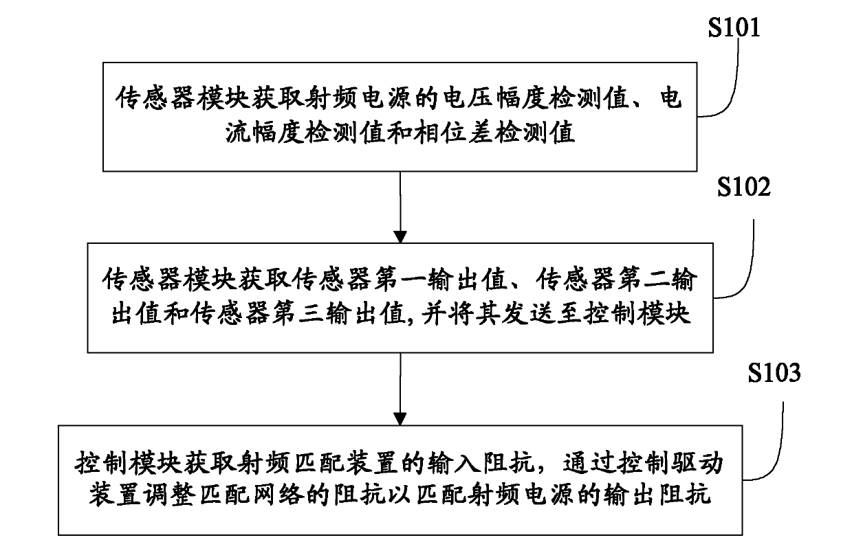
[0066] Such as figure 2 As shown, the radio frequency matching method for the plasma chamber according to the embodiment of the present invention includes the following steps:

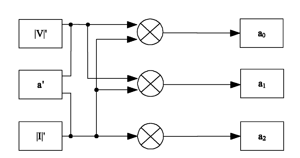
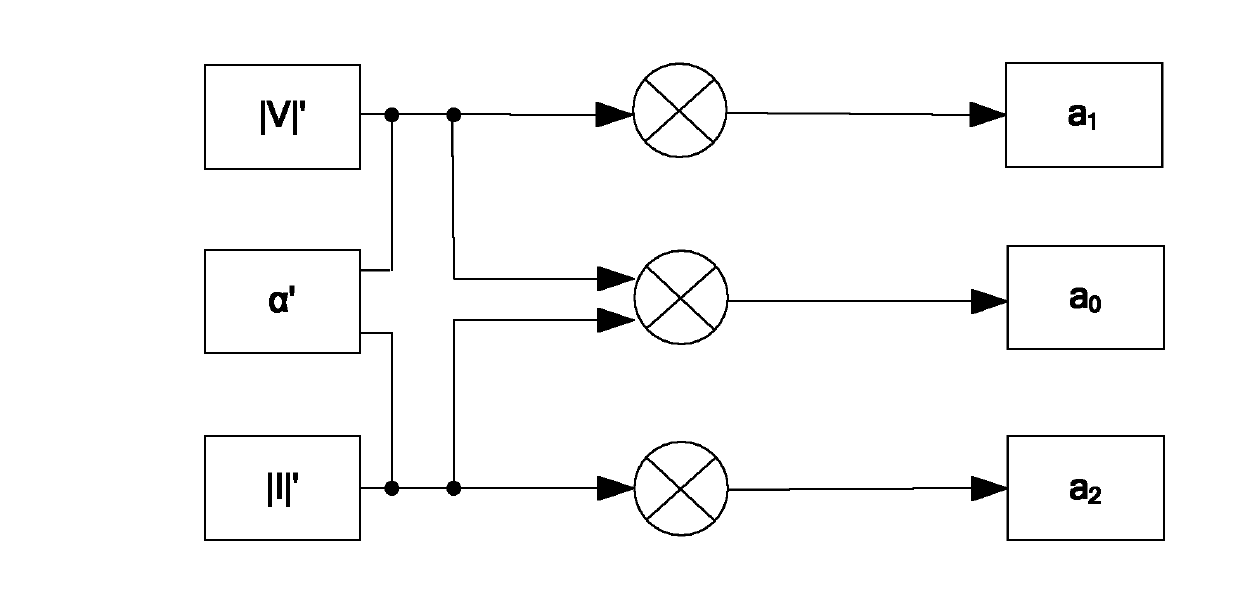
[0067] S101: The sensor module acquires the voltage amplitude detection value |V|', the current amplitude detection value |I|' and the phase difference detection value α' of the RF power supply; the phase difference detection value α' here is specifically the detected voltage and the detected The phase difference of the current;

[0068] S102: The sensor modul...


PUM


Abstract

The invention discloses a radio frequency matching method and device, as well as a plasma device. The method comprises the steps as following: a sensor module acquires the voltage amplitude detection value, the current amplitude detection value and the phase difference detection value of a radio frequency power supply; a first sensor output value is acquired according to the voltage amplitude detection value, the current amplitude detection value and the phase difference detection value, a second output value is acquired according to voltage amplitude detection value, a third sensor output value is acquired according to the current amplitude detection value, and the first sensor output value, the second sensor output value and the third sensor output value are transmitted to a control module; and the control module acquires the input impedance of the radio frequency matching device according to the first sensor output value, the second sensor output value and the third sensor output value, and according to the input resistance, the resistance matching with the network is adjusted through the controlling of an execution module so as to match with the output resistance of the radio frequency power supply. According to the invention, the operation type and the operation time of the input resistance are respectively simplified and shortened, and the measurement precision of the sensor is improved.

Description

technical field [0001] The invention relates to semiconductor technology, in particular to a radio frequency matching method and device, and plasma equipment with the same. Background technique [0002] In the semiconductor manufacturing process, plasma is widely used in the production process of semiconductor devices. In a plasma etch system, an RF power supply supplies power to the plasma chamber to generate the plasma. Plasma contains a large number of active particles such as electrons, ions, excited atoms, molecules and free radicals. These active particles interact with the wafer placed in the cavity and exposed to the plasma environment, so that the surface of the wafer material Various physical and chemical reactions, and then change the surface properties of the material, and complete the etching of the wafer or other processes. [0003] The operating frequency of the commonly used RF power supply today is 13.56MHz, and the output impedance is 50Ω. The RF power s...

Claims


Application Information

Patent Timeline
Patent Type & Authority Applications(China)
IPC IPC(8): H05H1/46
Inventor 成晓阳武晔
Owner BEIJING NAURA MICROELECTRONICS EQUIP CO LTD
Why Eureka
Try Eureka